Part 1
– Specifications, Features and Overview
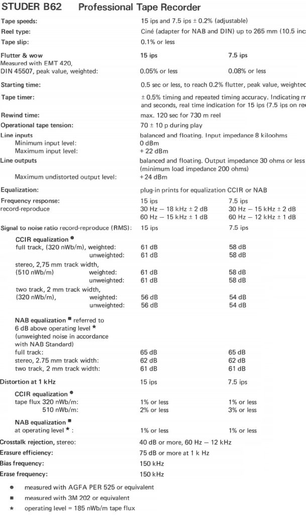
Specifications:
Features:
- Dynamic tape tension control
- Full roller tape path including scrape/flutter idler (later models)
- Dual stage mechanical brakes
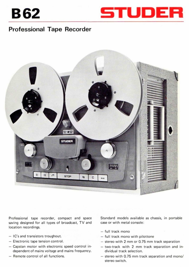
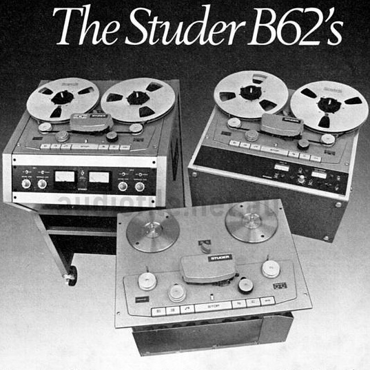
- Compact portable size with optional transport case
- Optional VU meter and audio level control panel
- Cassette style plug-in printed circuit boards
- Fully transistorised electronics without any monolithic IC’s
- Audio electronics shared with A80 master recorder
- Plug-in EQ modules
- Dual speed 15/7.5ips or 7.5/3.75ips
- 150kHz bias frequency
- Compatible with high bias tape
- High headroom
- Fully electronic transport mode switching
- Remote control option
- Cue mode
- Reproduce head flip-up magnetic shield (manually operated)
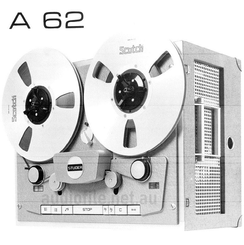
Compared to the Studer A62:
Compared to the previous A62 model the Studer B62 Tape Recorder/Reproducer is mechanically very similar. It has the same:
- Chassis and tape path
- Full roller tape path
- Plug-in head block assembly
- Enclosure, console and VU meter assembly
- Plug-in electronics card cage
- Dual stage mechanical brakes and dual pinch roller solenoids
However, the electronic design is all new. It now features:
- An improved tape tension servo
- Higher performance audio circuitry
- New power supply design
- Fully redesigned capstan employing a new generation Eddy current motor and sophisticated drive electronics replacing the A62’s 3-phase hysteresis-synchronous motor
- Higher frequency bias oscillator
Along with a number of mechanical improvements, including:
- Scrape/flutter idler (later models)
- Newly designed tone heads
- Redesigned timing indicator
The B62 also features additional options including:
- Mono version
- 0.7mm guard-band ‘butterfly’ heads
- Stereo & 2-Track configurations
Restoration Overview:
We recently acquired a lovely example of a Studer B62 but in need of a full restoration job. While in very good cosmetic condition, 40 years of use and the lack of it had seen things go downhill a bit. The B62 is a very rare model with a key target market of outside broadcasting or other portable applications, if you can call 40kg including its transport case, portable! But it also found widespread use in studios as a mastering recorder in the 1970’s & 80’s.
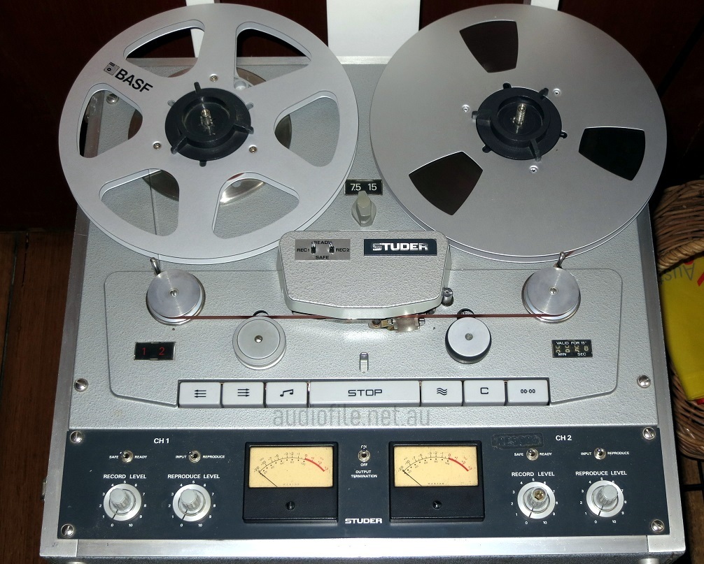
This particular machine is a 15ips/7.5ips 2-track IEC EQ unit with the optional VU meters control panel and transport case
A partial list of problems includes:
- No reproduce on one channel
- No record on one channel (not the same channel, ha!)
- Both channels have poor erasure depth
- One tape guide is damaged
- One record indicator not working
- One tape speed indicator not working
- A record level control knob cap is missing
- Pinch roller is perished
- Tape path roller bearings are noisy
- Some trimpots look corroded
- Tape guides not returning smoothly
- Brakes are noisy
- Transport case a bit tatty with some holes in the vinyl covering
- Transport case catch missing its keeper
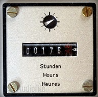
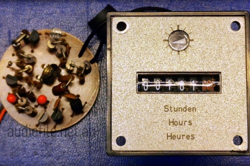
According to the hour meter, the machine had only seen 176 hours of record/reproduce use. (the hour- meter only runs when tape is contact with the heads during record/reproduce) But inspection of the sound heads suggested otherwise with an amount of wear indicating more like 500 to 1000 hours service. Further inspection showed that a faulty hour-meter could be added to the list of problems!
Slightly wishful thinking
Before the love
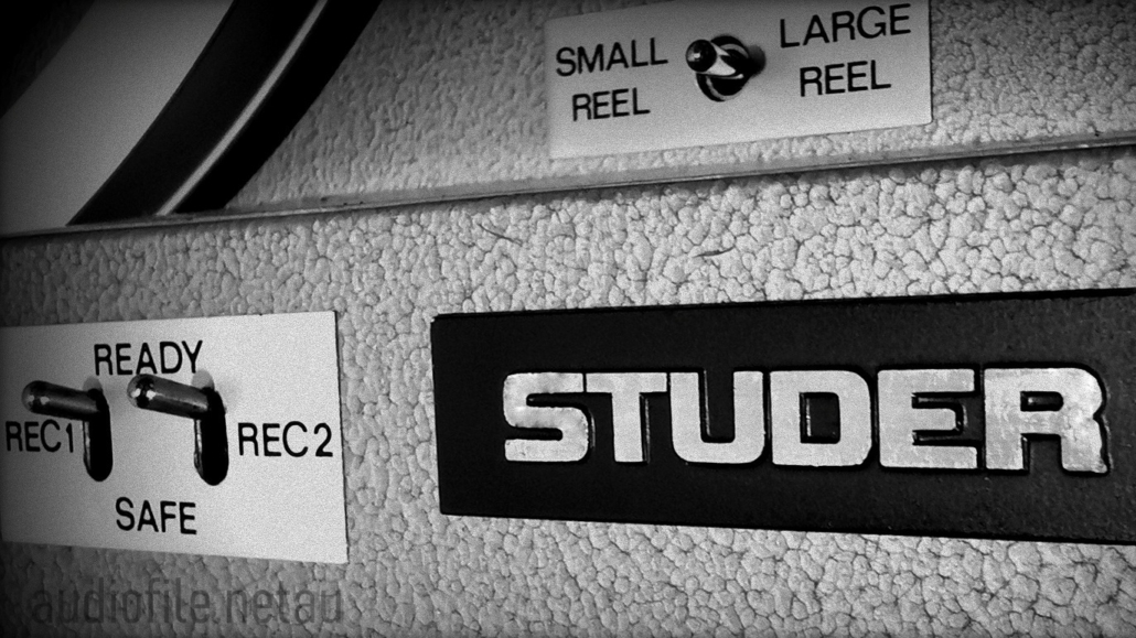
Look at that beautiful hammer tone finish!
Construction:
‘Built like a tank’ is a phrase often thrown around, but in the case of the Studer B62 is actually meaningful; this thing really is built like a tank!
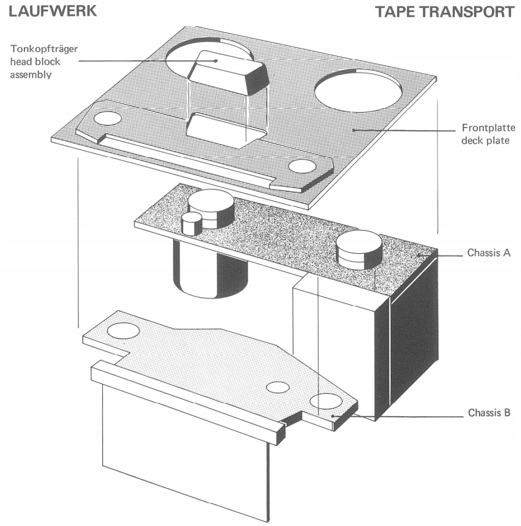
Three separate chassis elements are held together in a sandwich. Each of the chassis elements is made from cast aluminium alloy and the three pieces held together make an exceptionally rigid platform for the tape path.
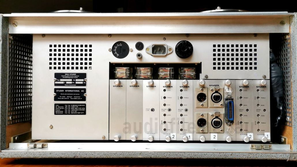
The electronics are housed in two card cages, one for the transport control circuits and another for the audio circuitry. An additional transport circuit board is mounted at the bottom of the machine that also forms part of the integral transport switch mechanism
Top of the Studer B62 showing the audio card cage
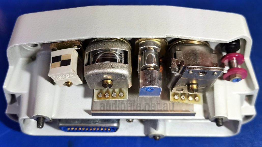
B62 Head block – Clean!
Soundheads:
The sound heads, although showing some wear looked in good shape with the wear marks evenly distributed across the face of the head, and this along with the factory sealing paint still intact on the head-stack screw heads, made it clear that the heads are original and the alignment never messed with.
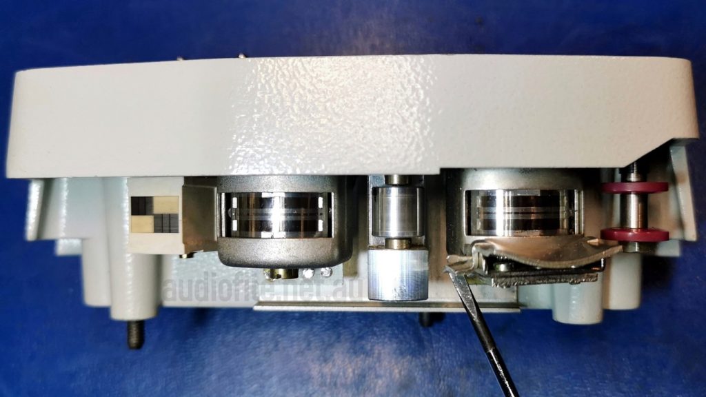
As you can see, the heads on this machine have a 2mm track gap and the the scrape/flutter idler is visible between the record and reproduce heads
Inductance:
A key parameter of sound heads is their inductance which is turn a function of the number of turns of wire and the head gap and an inductance measurement at 1kHz gives a very rough proxy for remaining head life. Manufacturers data gives inductance for new heads, and heads in good condition should be close to the new value. There is no point in measuring the DC resistance of a sound head, it doesn’t tell you anything and in some cases the DC current passed through the head can magnetise it, negatively affecting its performance. Although with modern multimeters, the current passed during a DC resistance measurement is so small that damage from magnetisation is unlikely. If you are purchasing replacement heads always check the inductance before fitting. There are a lot of counterfeit sound heads around on various auction sites so buyer beware!
Inspection under a stereo microscope and inductance measurements indicated that the sound heads have plenty of life left and as long as the tape path through the head stack wasn’t disturbed there was little benefit to relapping the heads at this time
B62 Head block with reproduce head shield held open
Head relapping:
Head relapping is a technique for resurfacing a sound head. Tape passing over a head will slowly wear a groove into the heads face, which is perfectly normal, the head slowly wears down and the head gap slowly opens up leading to a gradual reduction in high frequency response and head inductance
The head-block typically has numerous guides and rollers to ensure the smooth passage of tape across the head faces in a consistent and repeatable manner. However, if the tape path is changed by altering the height, zenith or significantly changing the azimuth of the head, the tape may be forced out of its groove losing contact with the all important head gap. Intimate contact is necessary for best high frequency perfomance as the wavelengths at high frequencies are so small
Of course in normal use the head azimuth will routinely be checked and adjusted, but the adjustments for optimum high frequency response and inter-channel phase response are tiny and will not affect tape contact with the head gap
Relapping will not restore the performance of a worn sound head. Once the material of the head has been lost due to wear it cannot be recovered. All replapping can do is to remove excess material and restore a uniform surface across the face of the head to give optimum contact between tape and sound head
For more information about relapping refer to an article first published in Recording Engineer/Producer magazine in February 1992 by John French & Bruce Borgerson and now available on Johns JRF Magnetics website http://jrfmagnetics.com/headtrip.html
Scrape & Flutter:
The Flutter/Scrape idler is responsible for providing a rolling surface for the tape immediately adjacent the reproduce head. It’s adjustment is critical for best scrape and flutter performance; if it protrudes too far into the tape path the tape will lose intimate contact with the reproduce heads gap, if it doesn’t protrude far enough, the functioning of the idler is impaired. Some years ago when equiring why an Ampex ATR102 was missing its scrape/flutter idler, the studio owner asserted that he had never had any flutter problems with machine!
Scrape and flutter are two critical aspects of the musicality of a tape recorder transport, the additional FM components of the recorded signal generated in combination with scrape and flutter effects can be heard as various sonic artifacts and determine the sound of a particular machine to a significant degree. Manufacturers go to extreme lengths to control flutter and tape scrape in their transports and careful alignment is needed for best performance. Once again, if there’s no need to mess with the tape path through the head block then it’s best left alone unless suitable test equipment is available for correct alignment
When you think about it, tape is a flexible medium, and when held under tension exhibits many of the same characteristics as a musical instrument string; a tape recorder really is a musical instrument in its own right!
But of course that’s not the intention, so rather than amplifying and shaping the vibrations transport engineers go to great lengths to minimise the effects of vibration
Part 2
– Mechanical Restoration
Brakes:
The Studer B62 Tape Recorder/Reproducer is unusual in its braking configuration as it has two sets of mechanical brakes on each reel table. The first set operate the same as other Studer machines holding the reels static when in stop mode or when power is lost. In later model B62’s such as this one, the second set of brakes come into play when changing from fast forward or rewind to stop mode and when power is lost.
Upon pressing the stop button, the first set of brakes actuate as normal but also the second set until the tape has completely stopped. Once stopped the second set of brakes is then released to allow the reels to be turned more easily by hand as is required when threading the tape. It’s an effective arrangement that doesn’t use electrical braking like later model Studer recorders.
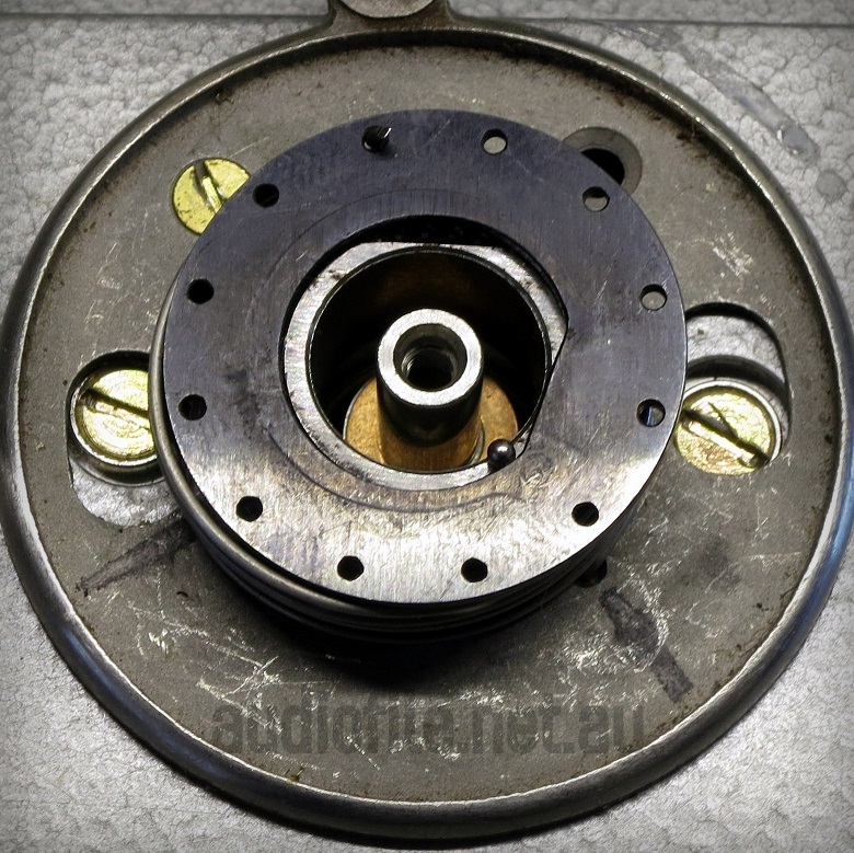
One of the downsides of a purely mechanical braking system is considerable wear of the brake linings. The brake bands are made of stainless steel and are pretty tough but the linings are more fragile friction material and can both wear out and become brittle due to age. On Studer machines of this vintage the brake linings will almost certainly need replacing.
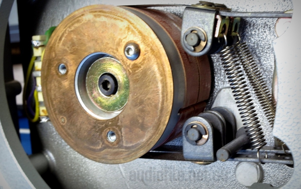
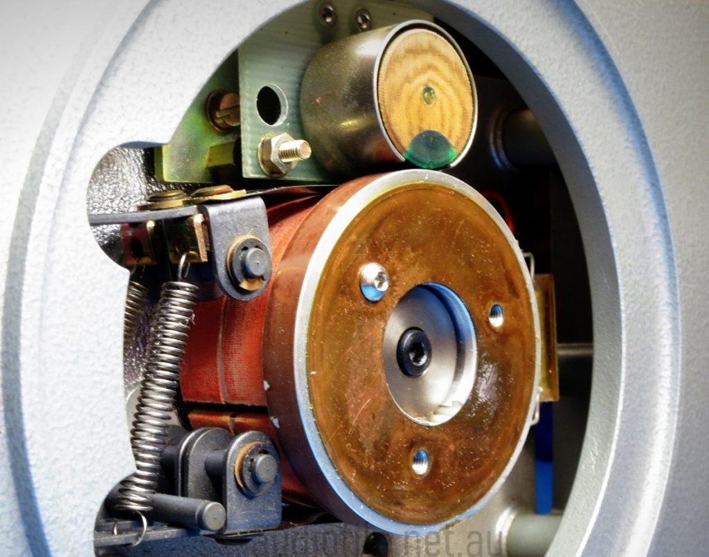
B62 Take-up reel brake assembly
B62 Supply reel brake assembly & tape tension tachometer
Take extreme care when working in the area around the left hand reel brake hub & its magnetic sensor making sure to demagnetise tools before hand
Tape Tension:
Tape tension in general and particularly during reproduce is another vitally important parameter that needs to be precisely controlled for best contact between the tape and the sound heads. It also subtly affects playback speed as the tape is elastic and apparent tape speed and hence musical pitch will decrease with increasing tension
The B62 along with other later model professional tape recorders measures tape tension dynamically to ensure constant tension and repeatable tape wrap over the head. Lesser and older machines often rely on tensioning the tape with a simpler constant torque method applied to the reel motors that results in varying tension across a reel of tape as it (un)winds and hence playback speed and musical pitch changes from the start to the end of a reel. Tape tension in the B62 is controlled to within +/-15% across a full to empty 10.5” reel of tape using a, sophisticated for its day, analogue, electronic servo
In addition to dual brakes, the left reel table also sports a tachometer for sensing reel rotational speed. The rotational speed is used to calculate the required motor torque to maintain constant tape tension. A magnetic head reads impulses recorded onto a piece of magnetic tape attached to the upper part of the brake drum
If you’re a company expert at making magnetic heads it probably made good sense at the time to build the tape tension sensor in the same way, but the risk of accidental erasure after a careless transport erase pass is high and in later machines this method of sensing reel rotational speed was no longer used
Bearings:
Turning attention to the bearings, there are a lot of them! The full roller tape path contributes to this: Two ball bearings in each reel motor, two in each brake drum, two each in the three tape guide rollers, two in the pinch roller, two in the tape tension arms, and two in the capstan motor (early models) or plain bearings (later models), a total of 20 bearings
Except for the tape tension arms, all of the other ball bearings are caged and easily replaced once access is gained. Unfortunately, some of the bearings are deeply embedded in the machine and require complete disassembly for access. Fortunately, the engineers at Studer made the machine modular and disassembly, while involved, is not too difficult
Replacing the bearings in the guide/pinch roller arms was necessary as, while not a high use item, the grease in the bearing had become hardened and restricted the ability of the pinch roller to smoothly move into position. The timing of pinch roller engagement is critical to smooth transport operation
The tape tension arm bearings are not caged and the ball races are simply held in place with an arm mechanism from either side of the sub-chassis. Extreme care is required during maintenance to avoid the balls spilling out and getting lost!
B62 Tape guide return spring and bearing assembly with one of the bearing balls trying to escape
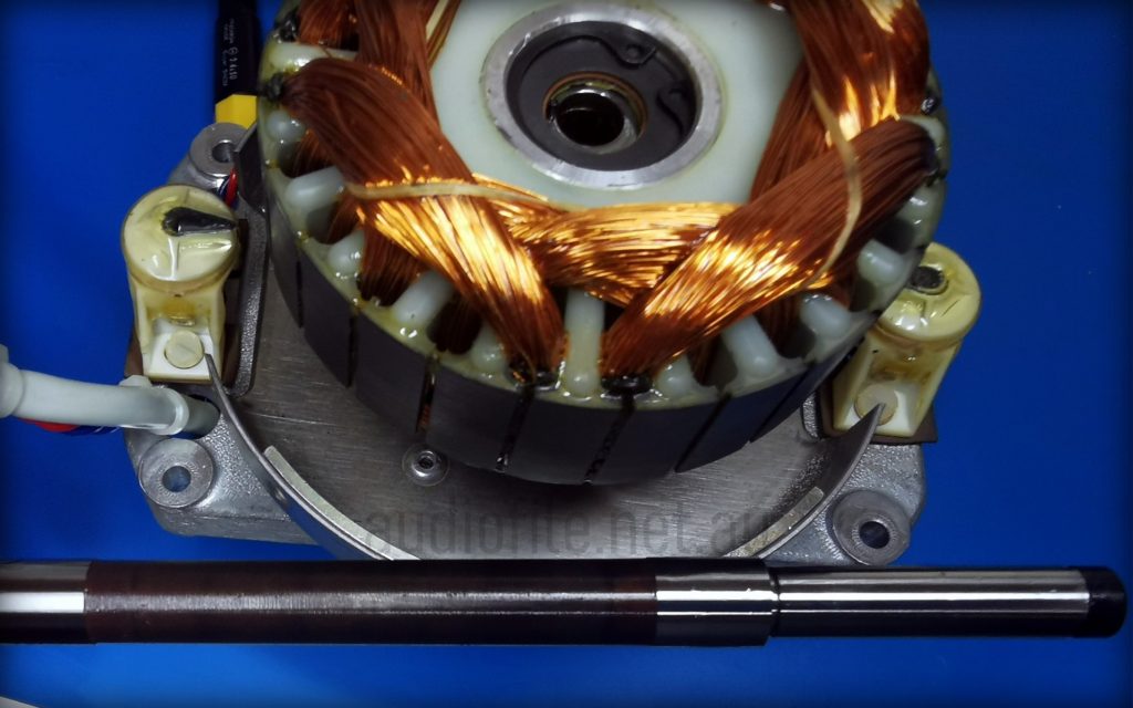
Capstan motor stator with windings along with capstan shaft. The two speed sensors can be seen on either side of the stator
Capstan Motor:
The capstan motor on this later model machine uses plain bearings rather than the older style ball bearings
The capstan motor was disassembled, checked for wear and found to be perfect so the bearings were cleaned, lubricated and reinstalled. The pinch roller and its ball bearings bearings were also replaced at this time along with any cir-clips that had lost their springiness
The capstan motor in the B62 is interesting as it was a newly developed Eddy current motor that overcame the major short comings of the hysteresis synchronous motors commonly used up until that time. The new motor is an induction motor that employs tachometer sensors and a servo system for speed accuracy superior to what was usual. It allowed the B62 and the A80 that also used the same system to achieve speed stability of 0.05%. The complete system is described in an Audio Engineering Society article by Arturo Stosberg in 1969, “A new concept for a capstan drive system for professional and home tape recorders”
Ball bearings vibrate slightly and are noisier than plain bearings and this can be recorded onto tape and affect reproduce noise performance as well. In the area around the sound heads only plain bearings are used for minimum noise. The sharp eyed observer may have noticed the use of ball bearings in the pinch roller on the B62, and while noisier, the ball bearing noise is effectively attenuated by the rubber roller
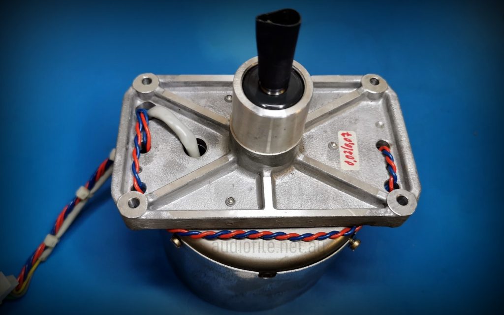
Adjacent: B62 Capstan motor assembly with protective sleeve over capstan shaft. Mu-metal shield can be seen over motor along with the motor stator wiring and twisted pair tachometer sensor wires
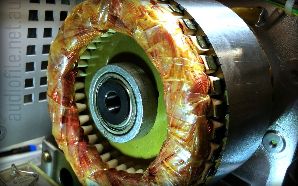
B62 Reel motor winding
Reel Motors:
The reel motors, similar to all Studer and Revox recorders of the era are both AC induction motors controlled by a dedicated tape tension PCBA that calculates correct reel motor torque over an entire reel of tape.
The reel motors were disassembled, checked for wear and found to need new bearings that were duly replaced
Dash Pots:
The dash pots, of which there are several, were all checked for correct operation in accordance with the service manual while the machine was apart as it’s impossible to adjust them with the machine fully assembled
And yes, we leaned this the hard way!
Dash pot assembly behind front panel attached to rear of tape tension guide arm
Pinch Roller Assembly:
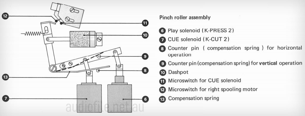
The mechanism that engages the pinch roller is interesting because it employs two solenoids to pull the pinch roller to the capstan. The first solenoid drives the pinch roller to within a few millimetres of the capstan and then the second solenoid finishes the job
By using the Cue button during stop mode the pinch roller can be left in a standby condition with one of the solenoids engaged so that when play mode is initiated and the second solenoid pulls in, the pinch roller contacts the capstan very quickly providing almost instant starting, great for recording punch-ins
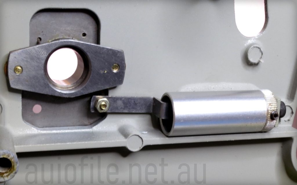
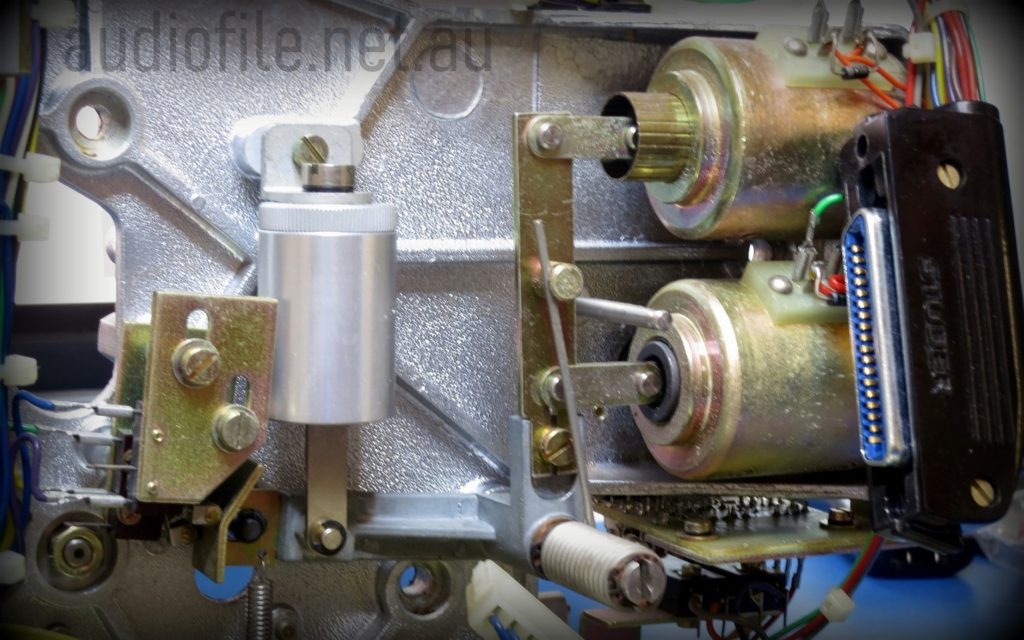
On the right of the picture the two pinch roller solenoids are visible along with the L-shaped arm they actuate that in turn rotates around a pivot at the centre of the ‘L’
The pivot point shows the concentric supporting coil spring that helps engage the pinch roller against gravity and the extended straight section at the of the spring that rests against a pin on the ‘L’ for vertical operation of the recorder and against a pin fixed to the sub-chassis for horizontal operation
At the other end of the L-shaped arm a dash pot and pair of micro-switches are visible, the dash pot damps the sudden motion of the pinch roller when the solenoids are engaged and the micro-switches cut solenoid current when the pinch roller disengages
A quirk of the pinch roller assembly is that it is affected by gravity and a support spring needs to be adjusted depending on whether the machine is used upright or laying down. Access is possible through the side of the machine without disassembly but unfortunately, is not possible with the machine in its transport case
Transport Control:
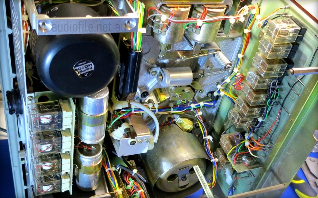
The B62 tape transport is controlled by a series of relays, and again the engineers at Studer aren’t shy about adding parts, a total of 13 multi-pole relays, 14 on later model machines. Some are accessible at the top of the machine without disassembly but others are hidden inside. On later machines the relay logic was replaced by a single IC
The transport relays can be seen in two columns, only the four on the left of the picture are readily accessible
Part 3
– Electrical Restoration
Electronics Overview:
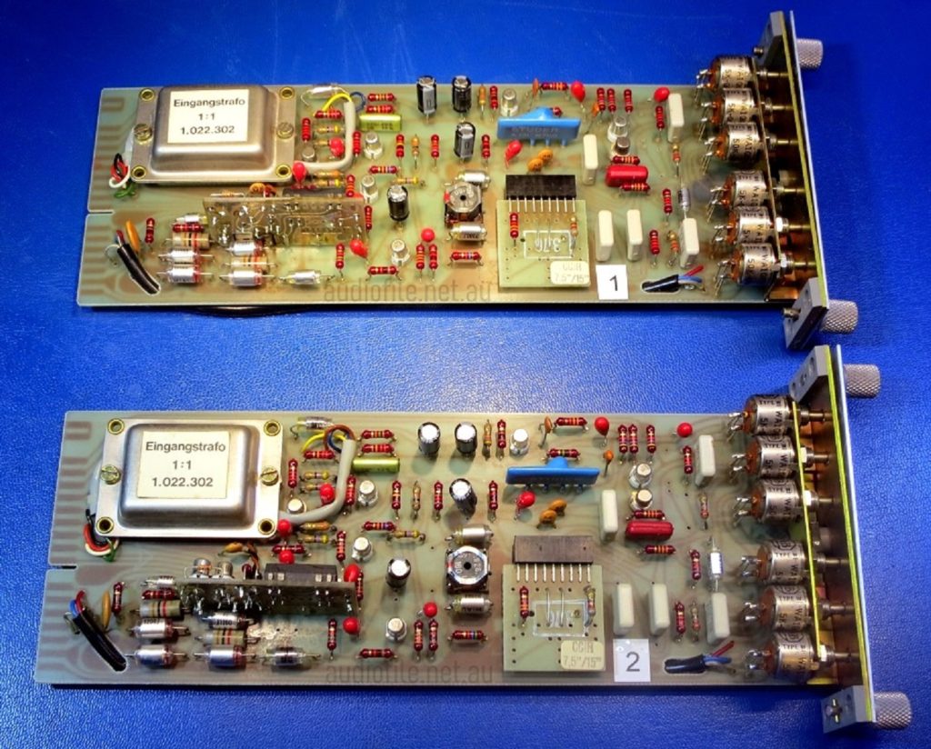
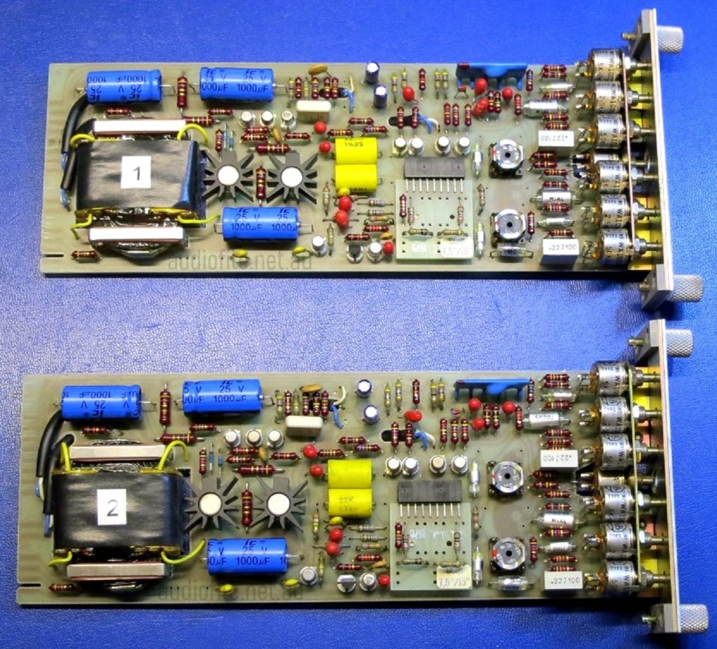
The transport electronics, as already discussed, use relay logic to control the interaction of the various transport functions with only a few discrete transistors employed to augment the logical functions of the relays. The capstan motor and reel motors are controlled by servos on their own separate circuit boards in a dedicated card cage and the remainder of the electronics is concerned with audio functions
The audio electronics in the Studer B62 Tape Recorder/Reproducer are basically the same as the original A80 MkI. Both machines share record and reproduce amplifiers and oscillators. The design is fully class-A using discrete transistors without any monolithic integrated circuits; while the Studer B26 uses the A101 integrated circuit, it is in fact just a discrete op-amp replacing a handful of transistors that would otherwise be included in the wider circuit
Supply rails are stabilised by IC regulators augmented with series-pass transistors for higher current capability. The supply voltages are +/-12V, enough for a maximum output level of +24dBm with the transformer coupled output stage. This ensures that even with modern high output tapes driven into saturation there’s enough headroom for an undistorted signal swing
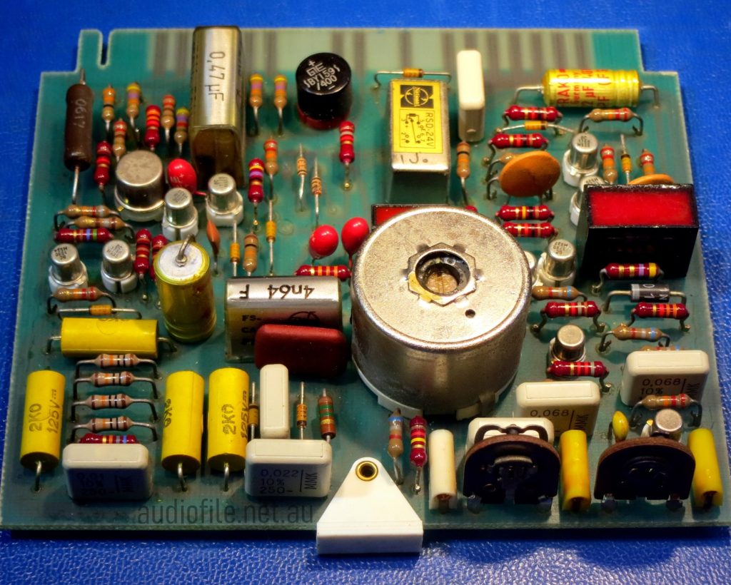
The oscillator providing bias current for the record head and erase current for the erase heads is provided by an L-C oscillator design running at 150kHz and able to swing 96VRMS. A set of relays direct bias and erase current as required by the state of the channel record enable switches. Different machine configurations ie 2-track, mono and stereo use different printed circuit boards. This particular machine is a 2-track type with three oscillator relays that can control each channel separately, so overdubbing is possible
A tape movement is sensed by an Eddy current sensor with a slotted wheel affecting the impedance to an L-C oscillator causing its frequency to change, the changes are amplified and rectified and serve as a control signal for the tape movement relay. The contacts of the relay then form part of the tape transport control logic
Other additions to the electronic design include a control panel with VU meters, source switching and input and output level controls. A nice feature are moveable rings around the level controls that can be rotated to a position indicating a reference audio level
Electronics Issues:
This particular machine had a number of electronics issues including:
– A relay switching audio to the record head on one of the two record amplifiers that had failed due to an open circuit coil which was replaced
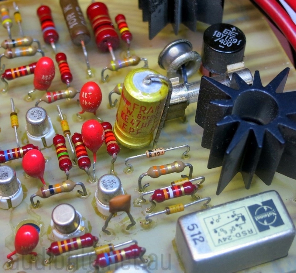
– Several of the Frako branded electrolytic capacitors are failed short-cicuit and several others measured with high ESR. As a precaution all of the electrolytic capacitors were replaced
– Poor erasure of prerecorded signals was found to be due to a failed tantalum capacitor on the oscillator board. This particular capacitor is highly stressed and so a failure is not unreasonable considering the recorders age
During audio checks a number of other tantalum capacitors were identified that had partially failed. The design of the B62 uses tantalum capacitors throughout the machine including in the audio path
While the electrical characteristics of tantalum capacitors are not ideal for passing audio they do have other unique properties including high reliability & low leakage current and the Studer engineers knew what they were doing when they chose tantalums
However, after seeing multiple tantalum capacitor failures it was decided to replace them all and after consideration of their function in the various circuits of the B62, low-leakage electrolytic capacitors were chosen as the best compromise replacement
While electrolytic capacitors may measure the correct capacitance value they may still not work reliably in a circuit due to high ESR. Even in cases where correct circuit operation is not affected by an high ESR, an increase in ESR is indicative of a capacitor that is losing electrolyte and is on its way to failure
Most LCR meters can measure ESR and this a much better metric for determining the condition of an electrolytic capacitor than simply measuring the capacitance. NOS electrolytic capacitor buyers beware!
At the time the B62 was conceived tantalum capacitors were the only types offering high capacitance in a small volume along with high reliability and low leakage currents. Nowadays, electrolytic capacitors can offer similar attributes and without the negative characteristics
Electronics Changes:
To change or not to change the types of components originally fitted by the manufacturer? The sound of a piece of gear is determined by the electronic circuit design and the components used
While the sound is mostly a function of the design in some cases the type of components can have a significant sonic effect, particularly in the case of capacitors
For a piece of vintage audio gear where the sound is associated with particular components the question becomes, is this something we want to mess with?
In the case of this B62 we were considering leaving the tantalum capacitors in circuit, but with so many failures observed this wasn’t an option, they had to go
Modern tantalum capacitor replacements were an option, but tantalum as an elemental material is a conflict resource and tantalum capacitors are now getting very expensive, and wouldn’t have been original anyway; so after much thought, the final decision made was to replace the tantalum capacitors with low-leakage electrolytics
Electronics Fixes:
The Studer B62 uses high quality sealed potentiometers for the audio adjustments that are frequently made but in other instances so called skeleton style trimmer potentiometers were employed for adjustments that were expected to be required infrequently
Some of the trimmers looked a bit corroded and testing showed that after sitting in one position for so many years smooth operation was no longer possible. As a precaution all of the trimmers were replaced with enclosed trimmers of a similar type and value
The non-functional hour meter is was found to have a failed transistor. It was an electrically highly stressed part and was replaced with a modern type with higher ratings that should be more durable in future
The motor run capacitors were all checked and found to be within spec so no replacements were made
The metalised paper capacitors or ‘Rifa bombs’ as they are sometimes called, were all replaced with modern equivalents. There are a total of six of these in the machine and they are all secreted in little hiding places throughout the chassis
Hour Meter with PCBA
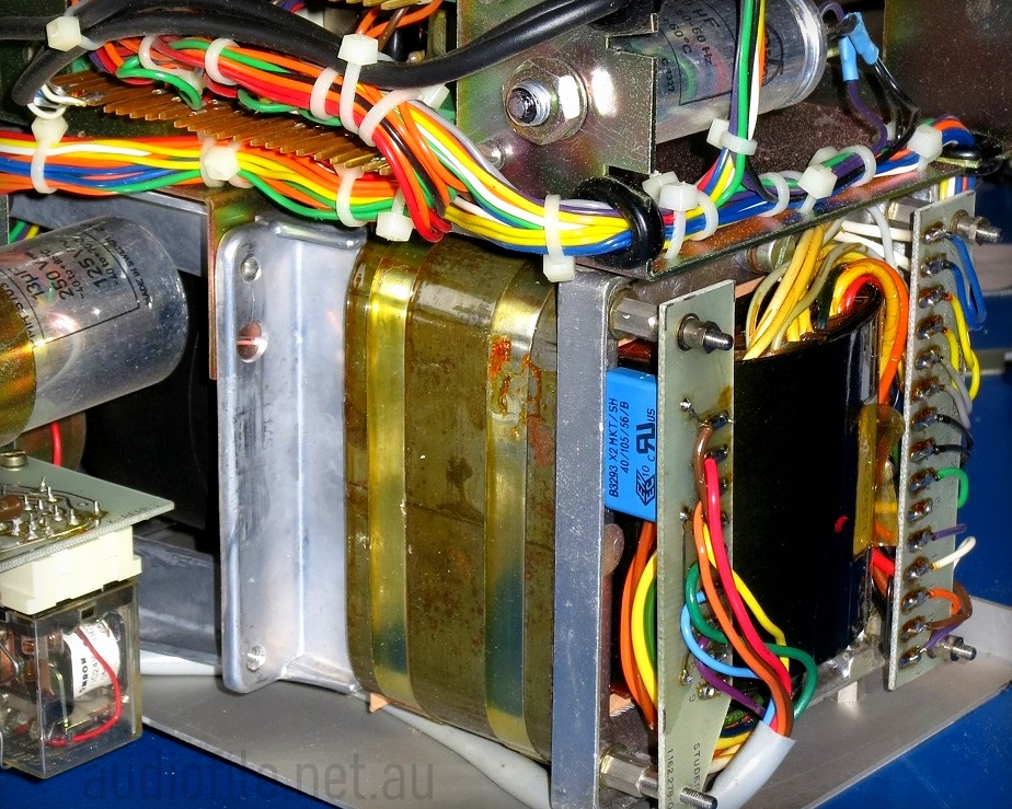
Capacitor (blue cased ployester cap) hiding under the power transformer
After all that:
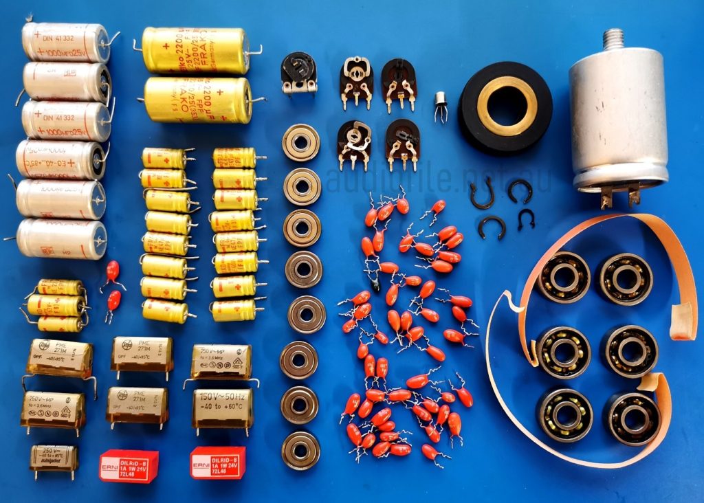
Quite a collection of replaced parts!
From top left:
- Axial leaded Electrolytics x19
- Metalised paper capacitors x7
- Signal relays x2
- Trimmers x5
- Sealed bearings x8
- Tatalum capacitors x 54!
- Transistor
- Pinch Roller
- Cir-clips x4
- Large Electrolytic capacitor
- Brake linings x4
- Unsealed bearings x6
- Whew!
Part 4
– Alignment & Measurements
Alignment:
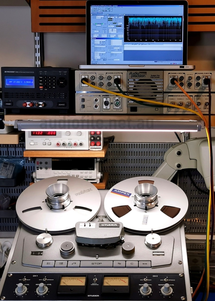
In keeping with the age of the machine and the mostly NAB equalised vintage tapes expected to be played on it we decided to bias the Studer B62 for RTM SM911 tape at a reference fluxivity of 250nWb/m equaling 0VU. Some of our pre-recorded NAB equalised tapes were recorded at 185nWb/m while others were recorded at 250nWb/m and most IEC equalised tapes were recorded at 320nWb/m, so 250nWb/m seems a good compromise. Because the B62 has so much headroom the much newer SM900 high output tape formulation run at hotter fluxivities, for example 510nWb/m, could also be used if desired.
The record and reproduce levels for both tape speeds were adjusted so the +4dBm was present at the connectors with the input and output level controls set to the nominal reference point of 6.2 on their 0-10 scale for an indication of 0VU on the VU meters. The B62 doesn’t have a ‘Cal’ switch so the reference level is set manually with the assistance of the indicator rings around each of the input and output level controls. Note that the output level setting will only be correct with output connectors connected to a 600R load, or in the case of high impedance load, with the termination switch set to the ON position.
Azimuth was easily adjusted with the aid of a modern 2-channel oscilloscope using signal averaging. Frequency response for both tape speeds was adjusted according to the service manual recommended settings. Bias oscillator level and frequency were checked and bias set to the tape manufacturer’s recommendations at both high and low tape speeds. Finally, the crosstalk adjustment was made and the machine labelled with the tape type, level settings and over-bias used.
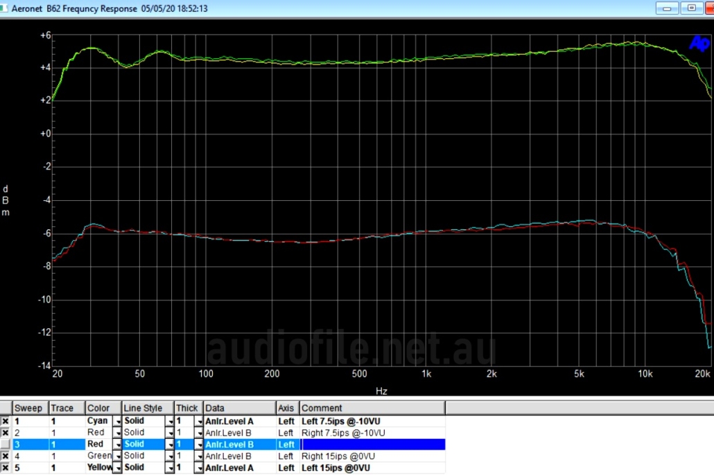
Frquency Response Measurements:
- RMGI SM911 Standard Bias Tape
- 250nWb/m Reference Level
- 600R Termination= ON
- Nominal electrical level = +4dBm = 0VU
- Level controls set to 6.2
Green/Yellow traces = Left/Right Channels
- Tape Speed = 15ips
- Level = 0VU
- Bias +3dB (RMGI recommendation) overbias
- Approximately +/-1dB from 22Hz -18kHz
Cyan/Red traces = Left/Right Channels
- Tape Speed = 7.5ips
- Level = -10VU
- Bias +6.5dB (RMGI recommendation) overbias
- Approximately +/-1dB from 20Hz -15kHz
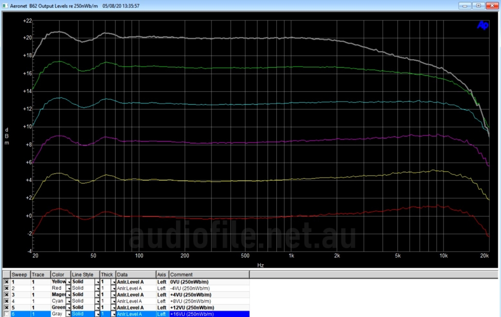
Maximum Ouptut Level:
- RMGI SM911 Standard Bias Tape
- 250nWb/m Reference Level
- 600R Termination= ON
- Nominal electrical level = +4dBm = 0VU
- Level controls set to 6.2
- Tape Speed = 15ips
- Bias +3dB (RMGI recommendation) overbias
- Yellow trace = Nominal Level (Red = -4dB)
- Pink trace = +4dB
- Cyan = +8dB
- Green = +12dB
- Grey = +16dB
Response is flat up to +10dB over the nominal level before any significant high frequency roll off is seen
Only one channel is shown
Signal to Noise Ratio:
Some earlier tests made with RGMI High Output SM900 at 510nWb/m reference level
- 600R Termination= ON
- Nominal electrical level = +4dBm = 0VU
- Level controls set to 6.2
- A-weighted filter used for all measurements
S/N Relative to nominal level of +4dBm
- Electronics Left: 99dB
- Electronics Right: 96dB
Tape Speed = 15ips, Bias +3dB (RMGI recommendation) overbias
- Left: 66dB
- Right: 67dB
Tape Speed = 7.5ips, Bias +6.5dB (RMGI recommendation) overbias
- Left: 63dB
- Right: 63dB
B62 Specification, CCIR 2mm guard band heads, relative to 320nWb/m:
- 15ips: 56dB, so relative to 500nWb/m: 60dB
- 7.5ips: 54dB, so relative to 500nWb/m: 58dB
Compared to Spec:
Machine exceeds its frequency response specs by about 1dB at both 15ips & 7.5ips
And exceeds its signal to noise ratio specs by about 6dB at 15ips and 5dB at 7.5ips
Modern tapes make a difference!
Part 5
Sound & Conclusions
Sounds:
So, how does it sound after all the love and attention?
Playing back some Decca second generation master tapes the B62 sounded superb. The tapes are beautiful recordings dubbed on a Philips EL3601 using Scotch 202 tape, intended for LP manufacture and dated 1969.
Recordings made on the B62 using modern tapes sound even better, no audible artifacts are detectable in recordings the apart from a small amount of tape hiss. The three dimensional sound stage of the recordings render the tape noise very benign, it disappears into the background even during low volume level musical passages. Switching between source and reproduce, apart from the obvious delay, make it difficult to tell the source from the sound coming off tape.
In use the Studer B62 Tape Recorder/Reproducer is a bit old fashioned. While performing superbly for recording and playback, the editing facilities are limited; there’s no auto-locator, switchable EQ, bias or other user friendly features. Just a mechanical tape counter to help with locating cue points. This is a machine that is set to record and left to do its job, which it does extremely well.
Further Information:
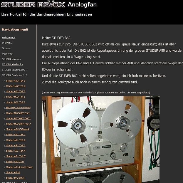
For more information on the restoration of the Studer B62 and other Studer and Revox machines please check out: https://www.analogfan.de/studer-bandmasch-ii/studer-b62-teil-1.html
In German, but with loads of great information for anyone interested in maintaining these wonderful machines!

