Part 1
– Specifications, Features and Overview
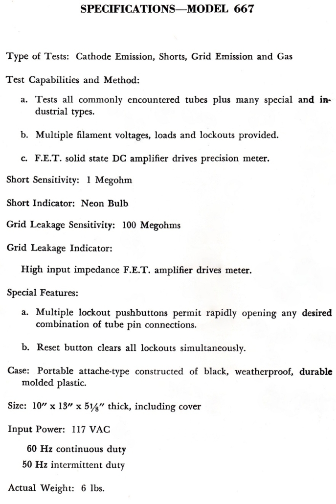
Specifications:
Features:
Before the love
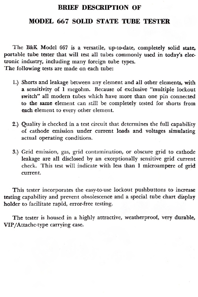
Overview:
Once you start renovating vacuum tube equipment a tube tester quickly becomes a necessary tool, not only for matching vacuum tubes but also to confirm that a tube is fit for service
There’s nothing worse than having a piece of gear with a fault and you’re not sure if the problem is a tube or the circuit its plugged into. A tube tester as the primary reference quickly sorts out the tubes that belong in the rubbish bin and those that belong in service allowing fault finding to continue with much greater confidence
An alternative fault finding method is by substitution where another hopefully known-good tube replaces the suspect device in the application circuit. But there is always some uncertainty about whether the replacement is definitely known to be good, and that doubt can confuse accurate fault diagnosis. A reliable tube tester eliminates that doubt. Additionally a faulty circuit can damage an otherwise good substitute tube so a tube tester can save money as well as time
Construction:
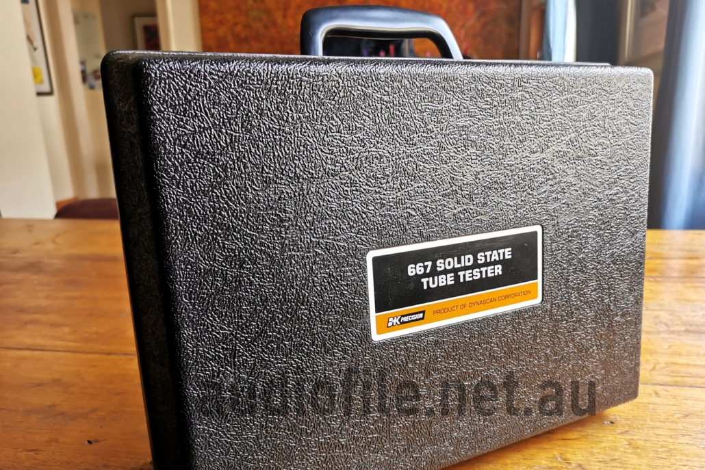
The B&K Precision 667 Tube Tester is constructed within double skinned plastic shell (highly attractive, weatherproof, very durable VIP/attache-type carrying case, according to the supplied description!) with both the base and folding cover roto-moulded from the same piece of plastic. It must have been quite a revolutionary construction method in its time.
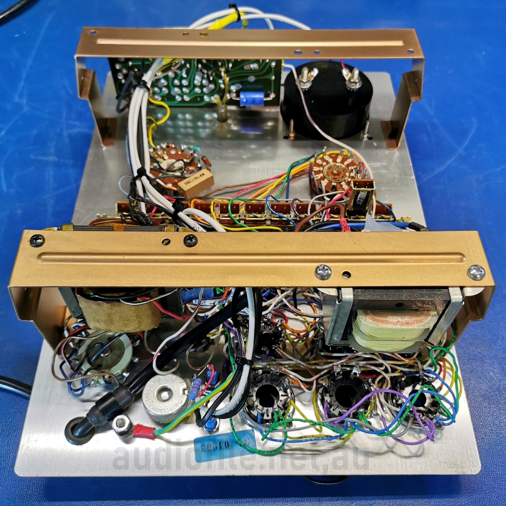
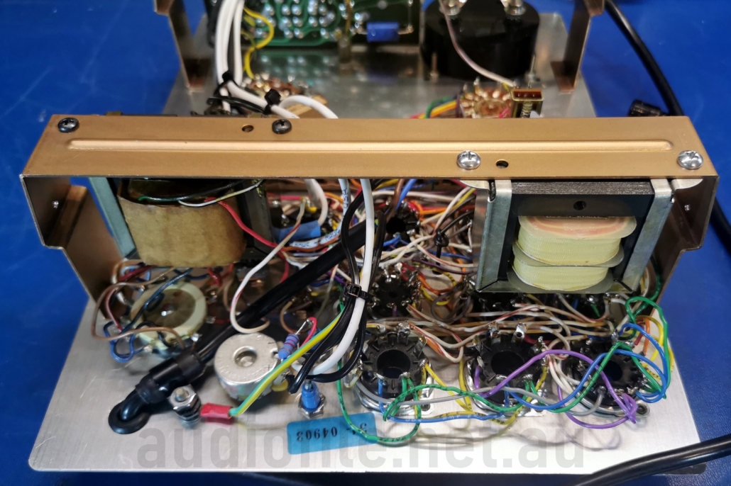
Most of the structural rigidity for the tester comes from the plastic shell and a fairly thin aluminium sheet front panel with a basic, two element folded sheet steel frame completes the assembly. The two frame elements screw into the plastic shell and the front panel attaches to the frame. It’s a very neat construction method that makes excellent use of the properties of the different materials. The plastic material is indeed very durable and may be a mix of polyethylene & polypropylene looking good even 50 years after manufacture.
In addition to the consideration given to the durability of the case, though has also been given to the durability of the internals. All parts are well secured and the sensitive moving coil meter movement is protected by a set of shorting contacts operated when the front panel power switch is set to the off position. The B&K 667 really looks like a service accessory that can survive almost any mistreatment and this is probably the reason for used items still looking almost new 50 years later
One weakness that was observed was the lack of a mechanical restraint on the relatively large and heavy, high power, wire wound resistors. These are secured by solder joints alone and may suffer fatigue failures after repeated shocks
Rear of front panel showing two bronze coloured frame elements that secure the entire assembly into the plastic shell
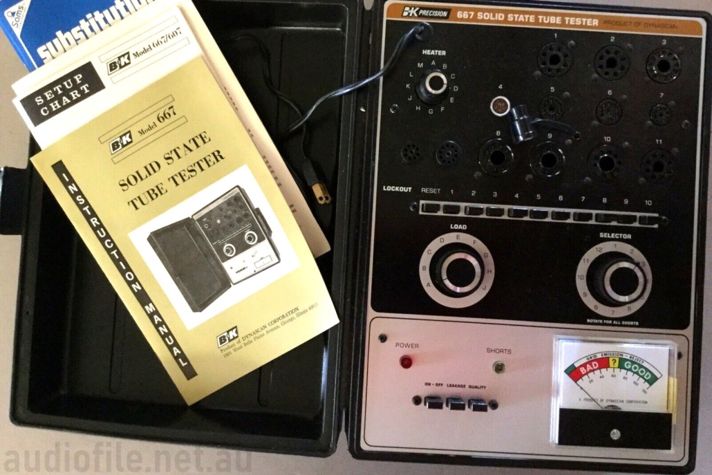
External shot of the VIP attache case -still looks like new
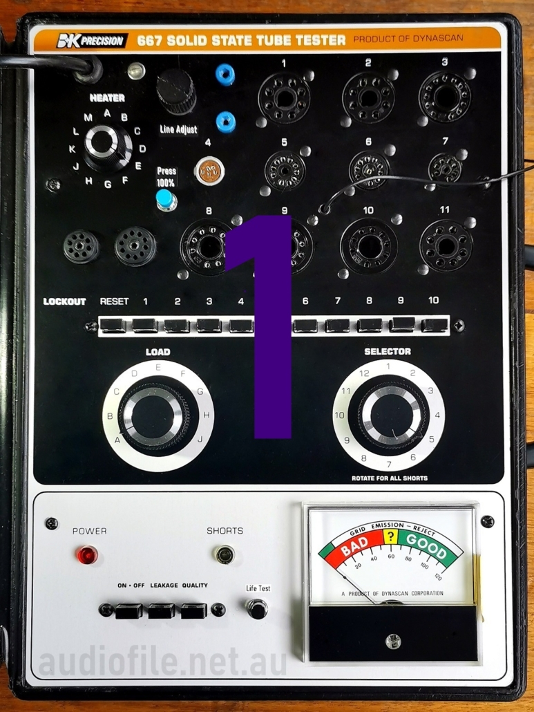
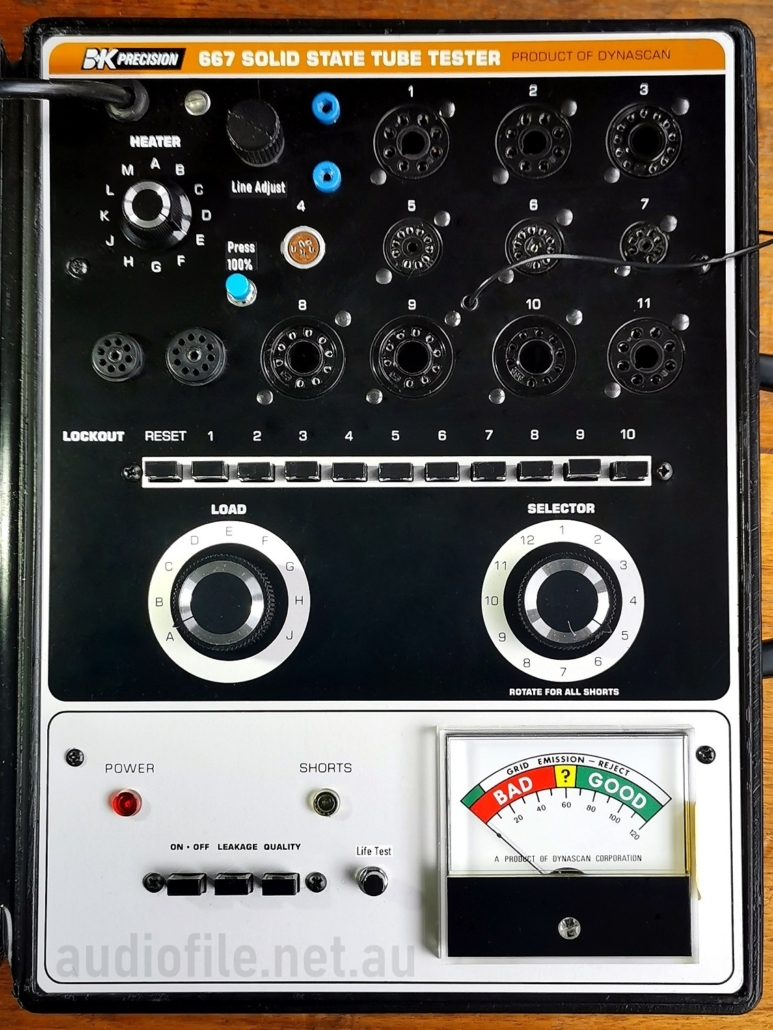
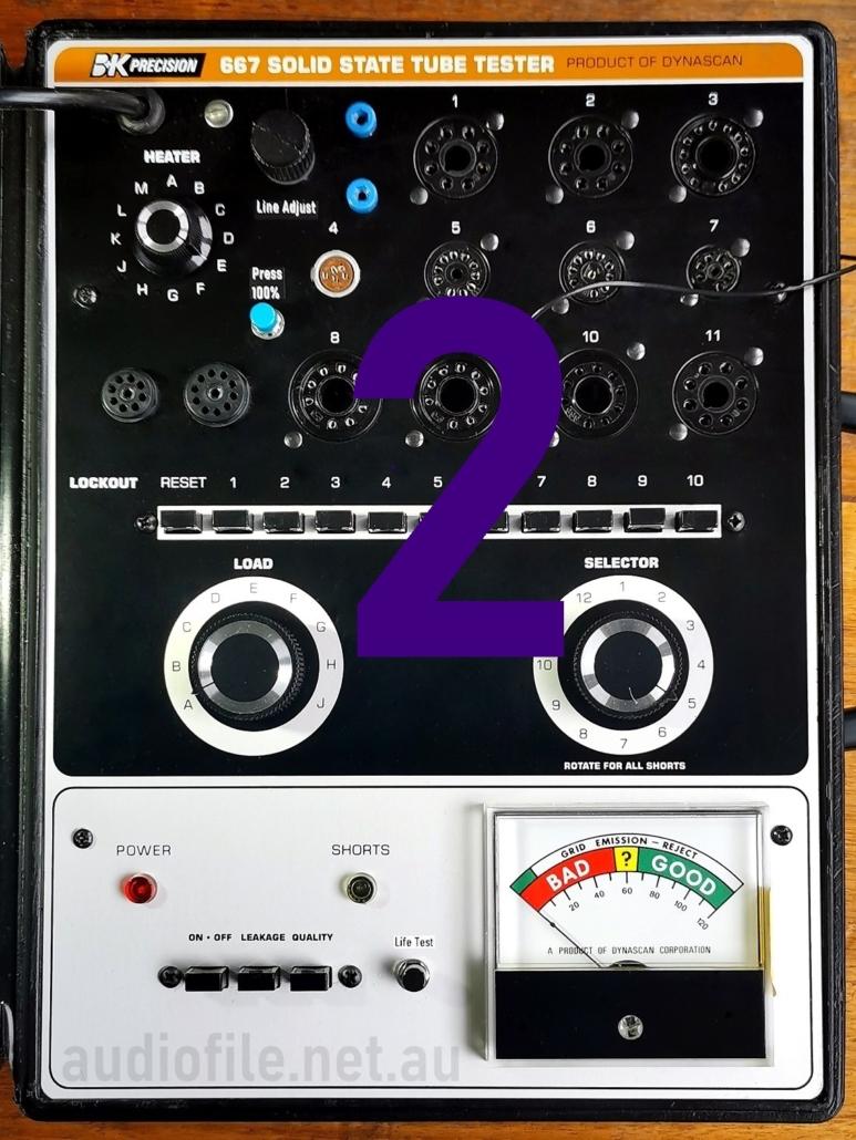
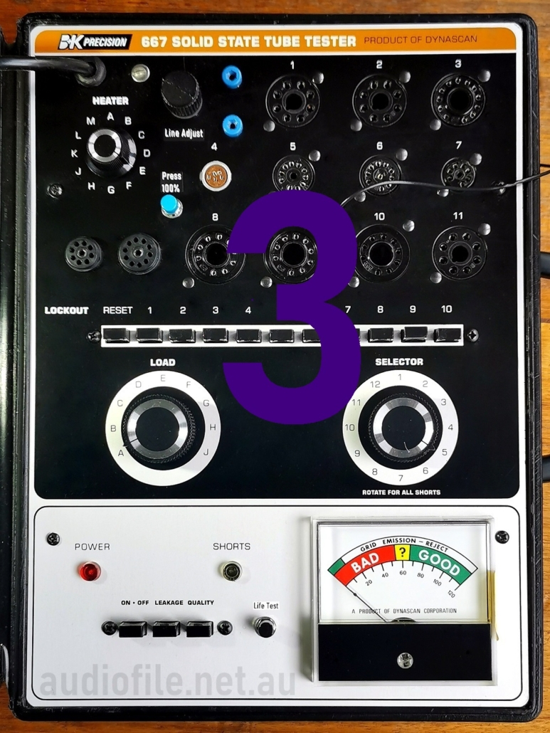
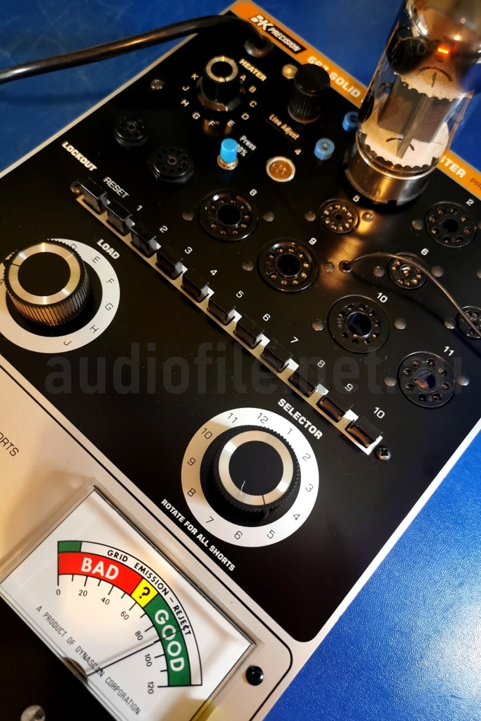
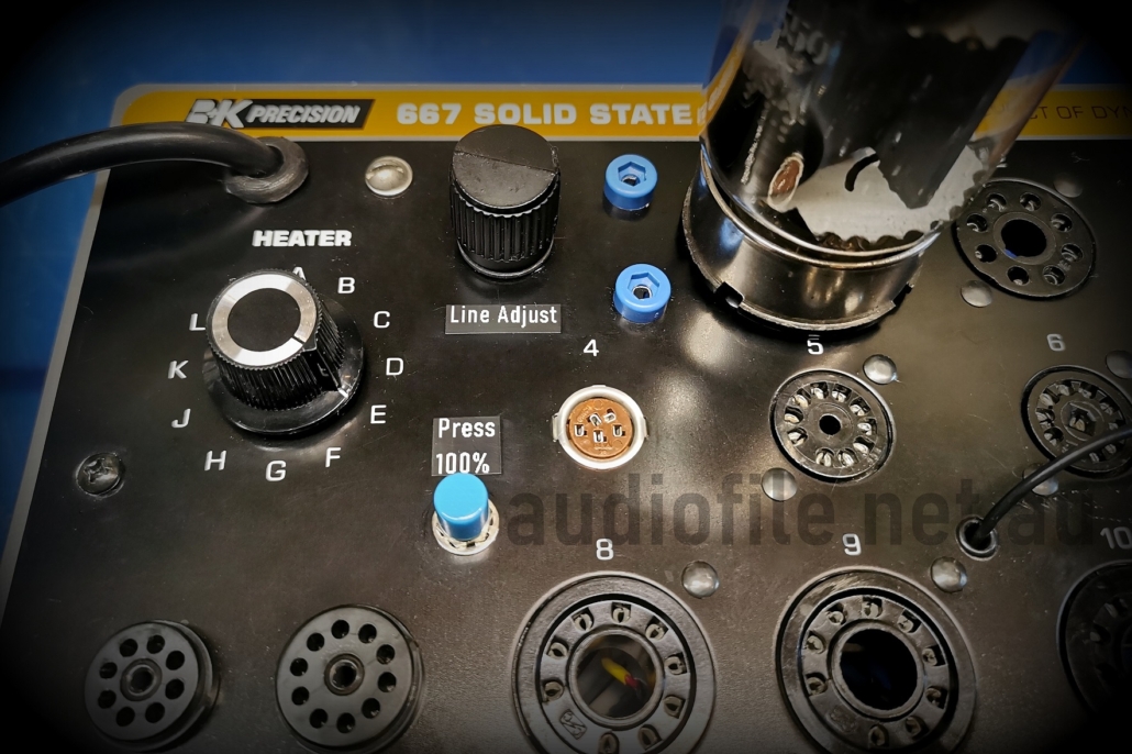
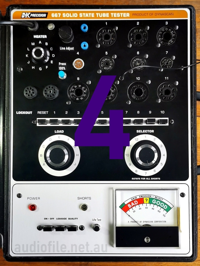
The front panel sports sockets for Compactron, Nuvistor, Decal, 10pin, 7pin miniature, 9pin Novar & Magnoval vacuum tubes and plate/grid cap is also supplied on a flying lead
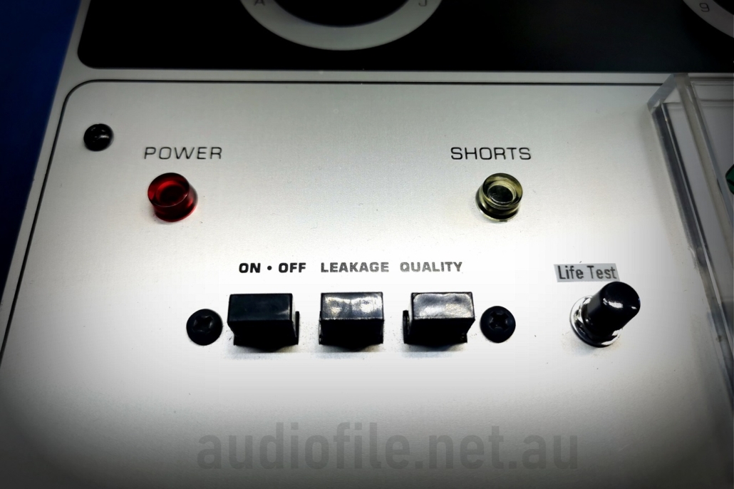
Front panel controls include high quality rotary switches for heater voltage, cathode load and tube type, along with a set of lockout push-button switches and a second set of test switches. Indicators include the front panel condition meter, a power indicator and ‘Shorts’ neon indicator. All clearly labelled and logically laid out. The switching functions of the various switches is very cleverly designed to maximise the number of compatible tube types whilst minimising the number of switching elements
Tube tester types:
There’s no shortage of vintage tube testers designs but few that appear on the used market in good condition and at a reasonable price nowadays
For serious work the vintage Hickok range is probably the best known and a great choice but they’re large, heavy, complex and expensive, but they do allow testing of a vacuum tube under similar operating conditions to those found in typical application circuits although interpreting the results can be a challenge. Finding one in good condition is also a challenge and they employ vacuum tube electronics so there’s a warm up time and associated operating point drift and of course with any vintage equipment ongoing care and maintenance is required
The modern equivalent is a PC based tube tester or more correctly a tube characteriser, such as the uTracer. https://www.dos4ever.com/uTracer3/uTracer3_pag1.html This is the perfect device for anyone developing vacuum tube electronics as all parameters are adjustable and complete parametric curves are displayed on a PC. There are no problems with component or operating point drift or aging and all results can be saved to a file for further analysis. Also, because it applies pulses rather than operating the tube under test continuously, tube elements can be driven well beyond their thermally limited ratings
A worthwhile and much smaller and simpler alternative is the plain emissions tester that while basic in operation is still surprisingly useful. They typically operate the tube under under test conditions emulating some of those found under actual operating conditions for many tube types but with the control elements tied to the anode to form a simple diode. Cathode emissivity degrades with load and age and is usually the determining factor in whether the tube remains usable so the test is a quick and simple way of sorting out weak devices
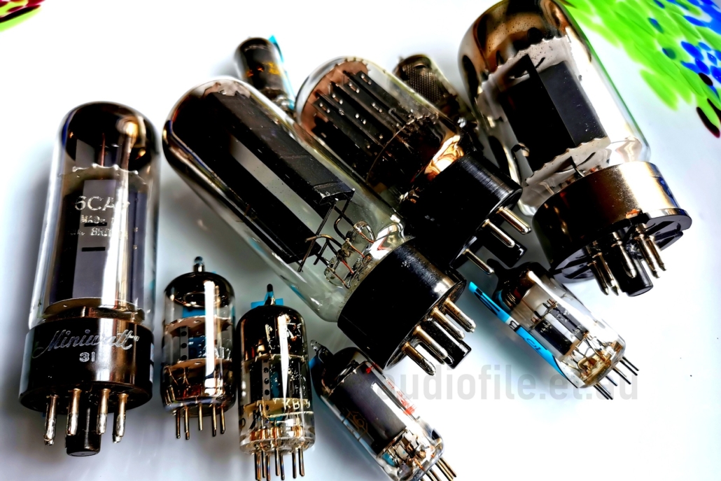
Tubes? We got ’em, but are they any good?
B&K 667 Emissions tester:
An example of a simple but high quality emissions tester is the B&K Precision 667 Tube Tester. These date from the 1970’s and have a FET input differential voltmeter circuit that is far more reliable and repeatable than older vacuum tube based designs
The B&K 667 has sockets for most of the modern tubes but not the older 4, 5 and 6 pin vacuum tubes, although these older tube types could be accommodated with an adaptor socket. Selector switches set the operating conditions for the tube under test including the filament voltage, applied AC grid voltage and cathode load resistance
Available filament voltages range from 1.6VAC to 52.5VAC, AC grid voltages range from 22VAC to 40VAC and cathode load resistance range from 140 ohms to 41.6k ohms, thus allowing emissions testing of almost all modern vacuum tube types
Operation of the B&K 667 is straightforward, the tube under test is found in the accompanying chart that identifies the positions of the various controls and the tube is tested for short circuits, grid leakage and cathode emissions in turn
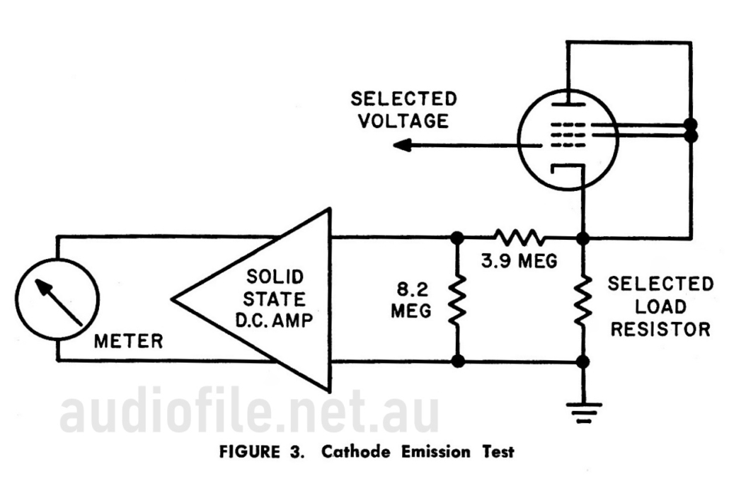
The emissions test circuit from the manual shows the way the test is performed. The tube under test has all of its grids except for the control tied together along with the cathode and anode to form a diode. An AC voltage is fed to the control grid and electrons flow from the cathode to the control grid during the AC half cycle when the grid is more positive than the cathode
All of the current flowing during a basic cathode emissions test passes via the control grid and this can be in excess of 200mA peak for power tubes although no mention of this being a problem is made in the instructions. The emissions test is performed only for a short time by pressing a momentary action push button switch so there is probably little concern about stressing the fine grid wires
In addition to the emissions test the B&K 667 also has comprehensive shorts test able to find any internal short circuits as well as a highly sensitive grid emissions and gas test
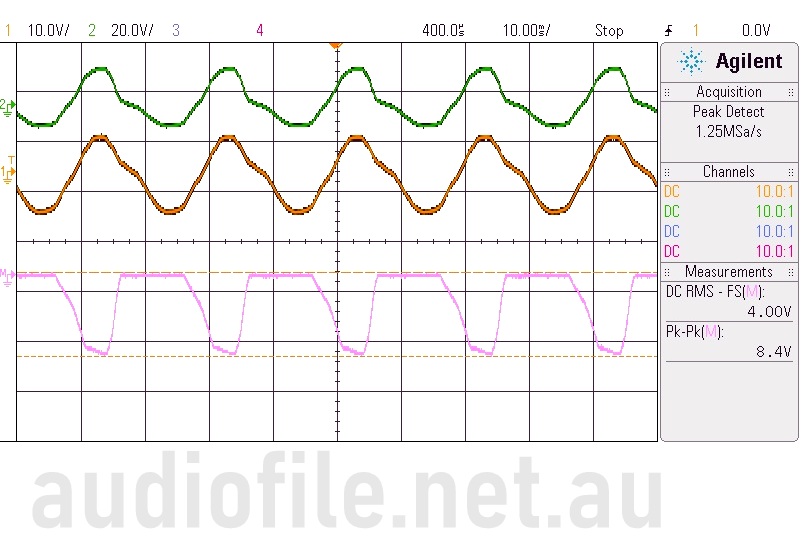
In order to actually measure the electron current flowing out of the grid during the emissions test, a 12AT7 plugged was plugged in to the tester and the differential voltage across one of the two 220 ohm cathode load resistors was measured
The green and yellow traces are the voltage on each side of the resistor with the pink trace being the difference of the two. Current can be seen to flow during the half cycle when the grid is more positive than the cathode and peaks at about 38mA
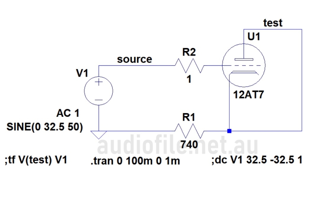
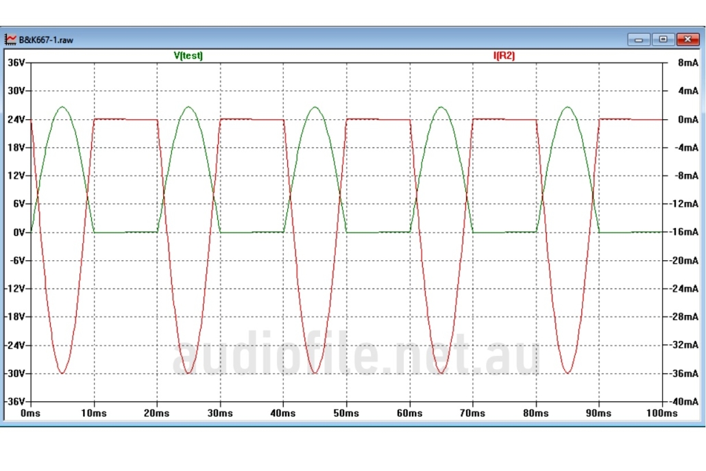
Out of interest, the circuit was also simulated using a model of the 12AT7 and it showed excellent agreement with the in-circuit measurements, slightly surprising given the unusual mode of operation for the tube, but indicating the validity of the model
Simulated equivalent circuit of a 12AT7 being tested for cathode emissions in the B&K 667
Flow of control grid current peaking at 36mA when the grid becomes positively biased
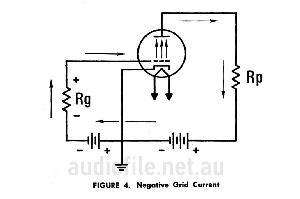
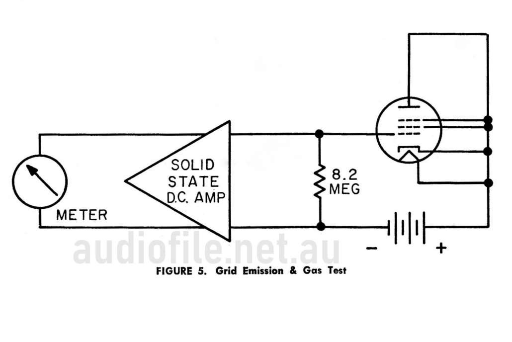
The grid emissions test checks for small currents flowing from the control grid due to cathode material deposited on it during operation of the vacuum tube. The effect is a minute flow of electrons into the grid element from the external circuit which because of its direction cause the grid to become more positive than intended which in turn can upset the biasing of sensitive circuits including those employing high value grid leak resistor
Such circuits are found in sensitive RF receivers and not in the relatively low impedance circuits of audio frequency amplifiers. Similar in effect is gas current where remnant ionised gas inside the tube recombines with electrons from the negatively biased grid causing control grid current to flow again sometimes causing high impedance circuits to misbehave
The circuit in the B&K 667 biases the vacuum tube under test beyond cutoff so that if any grid current flows it biases the tube into conduction and this is indicated on the panel meter. The currents involved are in the range of tens of nano amps and calibration of the grid leakage current measurement circuit circuit requires the use of a very high value 100M ohm resistor
Part 2
– Restoration
Checks:
The particular B&K Precision 667 Tube Tester undergoing refurbishment was obtained in very good condition, cosmetically very nice and internally very clean
Before switching anything on all of the carbon composition resistors were check and any that were out of tolerance or close to being out of tolerance were replaced. At the same time all of the electrolytic capacitors were replaced and the other capacitors tested for value and dissipation factor and ESR, all were OK. The switches were inspected and a very small amount of contact cleaner and lubricant applied. One needs to be careful applying fluids to the switches in tube testers such as this one with its high sensitivity grid emissions test as any leakage across the switch contacts can render the test inaccurate
The power transformer was checked for leakage as a proxy for insulation resistance and with use of a variac the mains input voltage increased to the nominal 117VAC required. Voltages around the internal circuitry were checked against the schematic diagram and everything seemed OK
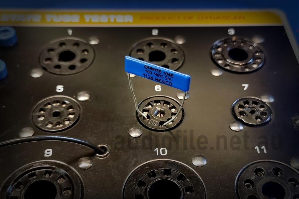
100M ohm resistor used for Grid Emissions calibration
Calibration:
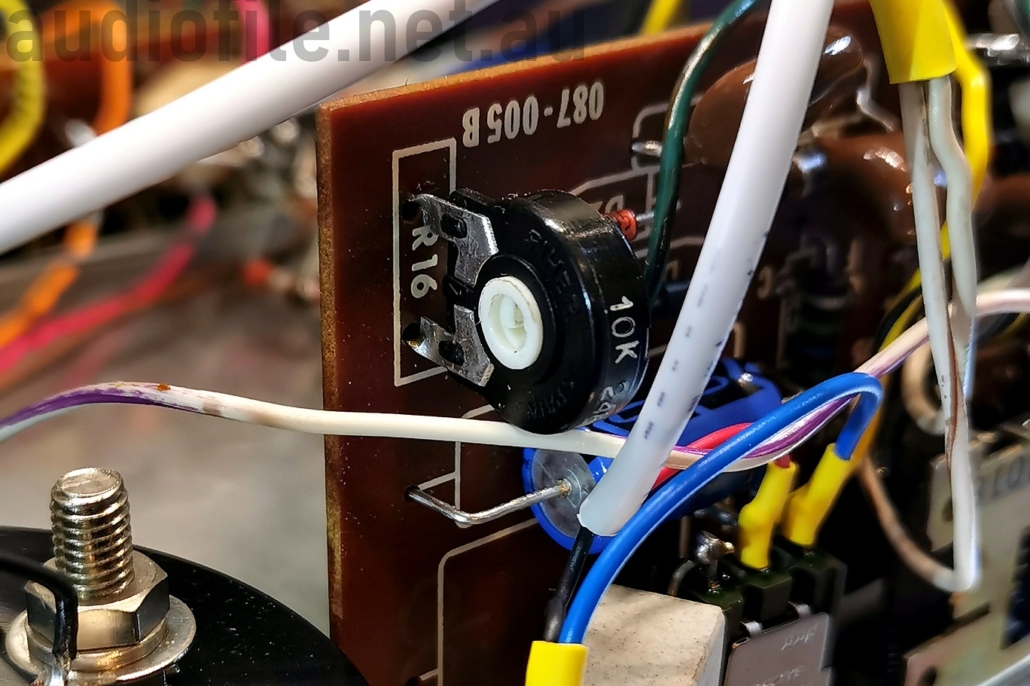
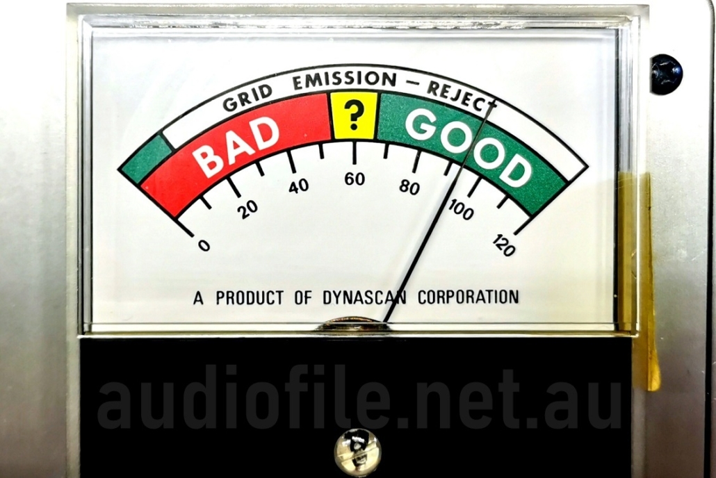
Calibration is very straight forward, first the leakage test circuit is calibrated with a 100M ohm resistor placed in the indicated socket pins and the selector switches set as indicated. The 10k ohm trim pot R16 is adjusted so that the front panel meter reads at the mark between the green and white partition of the “Grid emissions – reject” scale
This is described in the user manual, and interestingly, an addendum included with the manual corrects the manual but seems to then incorrectly identify the black and white partition of the scale!
Next the ‘Shorts’ test circuit is adjusted so that the ‘Shorts’ neon lamp just starts to glow when a 1M ohm resistor is inserted in circuit
In common with many tube testers, sometimes what appears to be the incorrect filament voltage is specified in the tube charts. For example the 5V filament rectifiers require setting the filament voltage selector to position ‘D’ the same as most 6.3 filament tubes. The apparent discrepancy is accounted for by the higher current draw of the rectifier tubes pulling the filament voltage lower and closer to 5VAC
In fact none of the filament voltages are exact and the designers have cleverly used the minimum number of discrete voltages to minimise the number of transformer taps required. Further, the filament voltage accuracy is not a significant factor with determining the health of a vacuum tube, although a weak tube will exaggerate the effect of a lower than nominal filament voltage
A few tubes were tested and the results were in line with expectations. Once warmed up a tube indicates cathode emissions on the meter with a good tube typically giving a result of 80 or more on the scale, well into the “Good” green are
There are some exceptions to this rule of thumb and for particular tubes the tube chart lists a lower value as indicating a good device
This is not a deficiency in the tube or the tester but simply a case of the operating conditions chosen for the particular tube type not being optimal and therefore causing a lower meter reading. Vacuum tubes in poor condition are quickly identified as having low emissions are indicating in the red portion of the scale. Tubes in less good condition also cause the meter needle to rise more slowly and this can be another hint of emissivity problems
Part 3
– Modifications
Decisions:
Due to the lack of testers available on the Australian market a unit had to be obtained from the US. However, mains voltage and frequency in the US is very different to that available locally.
The B&K Precision 667 Tube Tester manual states that the mains input power is nominally 117VAC at 60Hz continuously or 50Hz intermittently. Australian mains is 230VAC at 50Hz in most states, in particular in Victoria
All tube testers are very fussy about mains voltage as it directly and proportionality reflects in meter readings. For emissions testers that are only operated for a pass/fail indication are less fussy but if the numerical scale scale is used as a measure of cathode emissions the mains needs to be close to nominal to be accurate
The refurbished tester works fine with a variac attached, but getting a variac out of the storage cabinet and continuously monitoring mains voltage is a pain so it was decided to modify the tester for use with 230VAC mains voltage
This is a more complicated process than for other types of equipment due to the multi-tapped filament voltages on the power transformer. Simply replacing the transformer is not possible and so the only option other than winding a custom transformer is to add a second power transformer to reduce 230VAC down to 117VAC
This is also less than straight forward because of the limited availability of transformers with exactly the right voltages ratios. Judging the transformer core by eye, the B&K transformer appeared to be rated at about 25VA. A suitable 30VA transformer with a 230VAC primary and 120VAC secondary was chosen and fitted to the tester
Original power transformer on the left and new & additional 230V-120VAC transformer on the right
New transformer:
The second power transformer could be fitted next to the existing transformer with plenty of room to spare and the mains wiring removed and replaced with a modern, 3-core power with Earth. The Earth wire was terminated to the front panel with a ring lug and screwed down along with star washers to prevent the connection vibrating loose over time. The cable was clamped so it could not be pulled out the tester accidentally, and a 0.5A fuse was also added in series with the mains active wire
As expected, initial tests with the modifications were unsatisfactory, this was because the added step down transformer is of relatively small size and its voltage regulation is poor. When small tubes with low power consumption are tested the voltage is far too high and when larger power tubes are tested the voltage sags, although still remaining too high. The excessive voltage from the step-down transformer to the original transformer causes the latter to partially saturate and this is exacerbated by the lower mains supply frequency of 50Hz additionally stressing it
A method of adjusting the mains voltage was felt to be necessary for a sound engineering design. This is commonly employed on many vacuum tube testers but not unfortunately on the B&K 667. Tube testers with the adjustment typically include a special extra primary transformer tap that allows the insertion of a potentiometer to adjust the voltage seen by the power transformer primary without wasting to much power
Of course the B&K 667 doesn’t feature such a tap so as an alternative a high power wire-wound series pot was added between the transformers. Considering the voltages obtained with the smallest tubes under test and the largest available, the 5U4 requiring a 3A filament supply, along with the lowest and highest measured supply voltages of around 225VAC to 244VAC, and the supply utility preferred voltage of 230VAC +6%/-2% it was calculated that a 5W potentiometer would be just large enough to cope. A switched potentiometer was chosen with the switch in series with the incoming mains supply that has added benefit of requiring the potentiometer be returned to the maximum resistance position before being switched off so that at next power up the voltage is at a minimum
Under normal circumstances operating components at the limit of the their ratings is not recommended and typically a derating factor would be applied, for a wire-wound potentiometer a derating factor of 30-50% would be appopriate. However, in this application, because it will only be the largest rectifier tubes that have the maximum current draw under worst case high mains scenarios, along with the fact that tube testers are only used intermittently in a workshop setting, it was felt that fully utilising the potentiometer power ratings was acceptable. It is unlikely that one hundred 5U4’s would be tested one after another in our workshop!
Once a mains voltage control is fitted there needs to be a way of monitoring the voltage is correct. As a front panel meter is already present on the instrument it is natural to want to use it to measure the mains voltage. A DPDT momentary push-button switch was added in series with the meter with the normally-closed circuit connecting the meter as normal and the normally-open circuit connected to a half wave rectifier and voltage divider supplied from the connection between the two transformers. The voltage divider was sized so that 117VAC indicates ‘100’ on the meter scale
In operation the push-button is pressed and the voltage adjusted while the tube is in its actual operating state ensuring the voltage is accurate to with +/1VAC, an error better than 1%. The voltage adjustment potentiometer and line adjust push button switch were mounted on the front panel physically adjacent one another so that the pair can be operated with one hand, the other hand used to operate the ‘Quality’ push button for best measurement accuracy
A pair of 2mm insulated sockets were also added to the tester to allow the voltage to be checked manually with an external meter as a double check that the voltage adjustment is still accurate if required. The 2mm sockets have a small recess that would normally not be considered safe with 117VAC on them, but the tube socket pins are similarly exposed and the tester is expected to be operated only by personnel with some experience so this was not felt to be a concern
Finally, a ‘Life’ test function was added to simulate the fall in emissivity with tube aging. This feature is found on Sencore brand testers and is a useful addition to test for weak tubes. If the emissivity of a tube as indicated by the front panel meter drops significantly when the filament voltage drops slightly, the tube may be suspect
The filament voltage drop is effected by adding a 1 ohm in series with the heater circuit. Of course the greater the heater current the greater the voltage drop and it might appear that the drop varies excessively between small signal and high power tubes, but in practice, while the power tubes do suffer a greater voltage drop, their much larger high emissions capacity cathodes mean the effect of the drop is smaller fraction of the total emissivity. A SPDT momentary push-button switch of suitable current rating was added to the front panel next to the ‘Quality’ push button with the normally-closed circuit connecting the heater circuit as normal and the normally-open circuit inserting the 1 ohm resistor in series with it
Part 4
– In the end
In the end, how does B&K Precision 667 Tube Tester function in practice on the bench? Perfectly! Within the limitations of a simple emissions tester, it’s compact and light weight, easy to set up and use, and tests all the tubes needed
Can’t ask for more than that!

