Part 1
– Features & Overview
Overview:
Not everyone needs a bulk eraser but when aligning tape recorders some procedures call for virgin tape. Using a fresh reel of tape for each test is impractical so a bulk eraser is the answer, taking a prerecorded tape and rendering it blank.
They’re also great for studios that reuse tape a number of times and need to be sure that all of the existing program material is gone. While tape recorder erase heads do a very good job of erasing program material, sometimes there are low level artifacts still audible, particularly at lower frequencies. By sending the tape through a bulk eraser and then following that with the recorders erase head no artifacts of a previous recording remain.
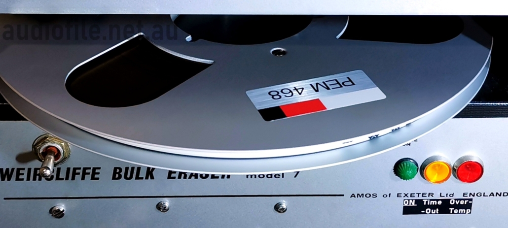
Looking around for an eraser like the Weircliffe Model 8 that is capable of handling 10.5″ reels proved unsuccessful, as it seems that used bulk erasers are even harder to find than good open-reel recorders. So when a Weircliffe Model 7 bulk eraser turned up at auction we decided to take a chance that it could be modified for use with 10.5” open reel tape….
Features:
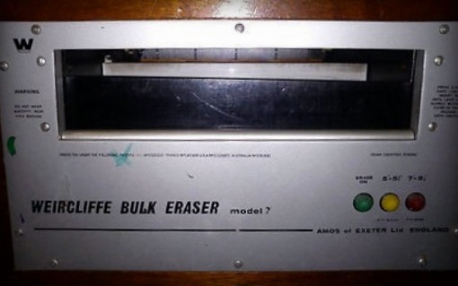
The Weircliffe Model 7 Magnetic Tape Bulk Eraser is capable of handling reels of tape up to about 8.5″ in diameter as well as audio and video cassettes up to and including U-matic cassettes.
- It erases tape!
- Uses lots of power, more on that later
- Makes lots of noise
- Weighs a ton, around 15kg
Condition:
The cosmetic condition of the eraser was a bit rough but it seemed operational making a lot of noise & humming loudly at the 50Hz mains frequency.
Before the love
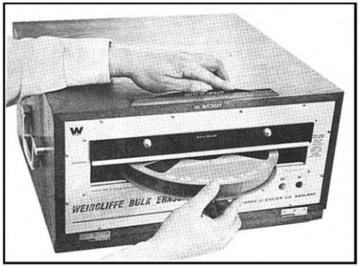
Operation of the Weircliffe Model 8 Bulk Eraser
Operation:
Operation is initiated by pressing down on a vertical blade poking out of the top of the unit that uncovers a slot in the front of the eraser allowing the insertion of reels or cassettes of magnetic tape
Tape Sled:
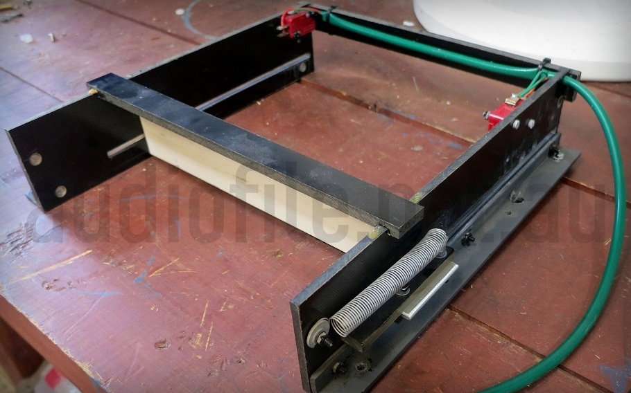
A spring loaded bar inside the machine gets pushed rearward as tapes are inserted and a couple of micro-switches mounted on the spring loaded bar cause front panel lamps to light as tapes are inserted far enough, first yellow and then red. The spring loaded bar is part of a sled assembly made entirely out of pieces of phenolic sheet glued together
Metal can’t be used in the area where the tape is being erased as Eddy currents induced into the metal parts would cause them to become extremely hot and vibrate vigorously
The front panel lamps are powered by a secondary coil winding producing a small, 1.5VAC voltage
Model 7 sled assembly showing the white coloured spring loaded bar & red micro-switches
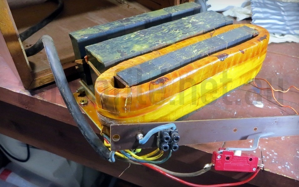
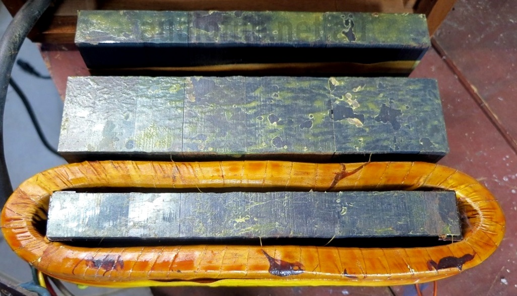
Eraser laminated core and coil with On/Off micro-switch and mains wiring
Core & Windings:
Below the sled assembly is a non-magnetic base supporting the tape to be erased and below that a heavy duty coil of wire is wound around a leg of a sectioned transformer core. AC mains current is applied to the coil winding which produces a magnetic field that is confined & directed by the transformer core. The coil is about 28cm wide and 5cm deep and the core is slightly less wide and extenders rearward into the eraser by about 16cm. The open nature of the core results in magnetic field lines extending up and out of the core towards the tape being erased. The core is made from laminated steel to reduce Eddy currents just the same as an ordinary, closed, power transformer core
The core is supported by a bracket that screws into a solid wooden housing, wood of course being chosen due to its strength and non-metallic properties.
Part 2
– Mechanical & Electrical Modifications
Mechanical Modifications:
The width & depth of the magnetic field directed by the core in the Weircliffe Model 7 Magnetic Tape Bulk Eraser is not wide enough to erase a full sized 10.5” reel of tape if simply inserted and extracted in a straight line, but if the tape is rotated across the core during operation the entire reel can be erased
The slot in the front of the bulk eraser was certainly too small to accommodate 10.5” reels of tape and the first thing to do was widen it. The wooden box housing the eraser has an internal width of 275mm, just wide enough for a 10.5” reel
After the sled assembly had been removed, the aluminium front panel was cut to make a full width slot. A power switch was added to the front panel along with a front panel Earth connection, the protection fuse changed for something more suitable, and the eraser tested for basic operation. So far, so good
But it was observed that the winding on the core of the eraser gets hot fast! After being on for only 5 minutes a thermal camera showed the hottest parts of the winding already reaching over 50C above ambient. The eraser was obviously not designed for continuous use. The thermal mass of the core cools the winding down pretty quickly when switched off so a 50% duty cycle, 5min on, 5min off is probably suitable in practice in normal office environments where the ambient temperature is about 20-25C
Eraser laminated core and coil winding
Electrical Considerations:
It quickly became apparent that the designers had given little consideration to the bulk erasers power factor as hooking up a power monitor indicated an operating current of 13.5A!
It’s likely that the designers decided that it was better not to add power factor correction to the device as that would increase its cost and instead push the responsibility of providing a power source capable of delivering enough current onto the final customer
In order to power the device from a normal, domestic, single phase, 10A power point the power factor had to be improved by adding capacitors to moderate the reactive loading of the eraser coil on the mains supply connection
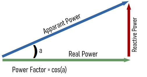
Power Factor Phasor Diagram
Power Factor:
Power factor is a measure of the ratio of real power to reactive power, real power is consumed to do work while reactive simply power circulates without performing work
From the network supply point of view, the ratio of real power to reactive power is ideally (1) indicating voltage and current are in phase as would be the case for a pure resistance. A low power factor evidenced by voltage and current being out of phase causes a large current to flow requiring larger conductor sizes that become a burden on network supply authorities
The phasor diagram shows phasors for real and reactive power with the apparent power being a combination of the two. Power factor is the cosine of the angle between real and apparent power, so for example, if the real and reactive power are of equal magnitude, apparent power is 1.4 times greater than either and the power factor is 0.7
For a pure inductance or pure capacitance without any resistance, there is no real power dissipated as all of the current flow is reactive. As inductance and capacitance have opposite phase angles they can be used in combination to improve power factor
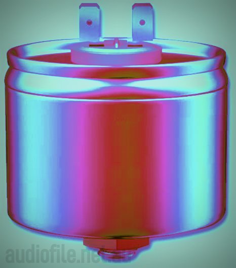
The power factor was improved by adding some motor-run capacitors in parallel with the coil winding, a total of 160uF could be easily fitted to the space at the rear of the wooden eraser box behind the core
Power Factor Correction Capacitors:
Capacitors aren’t the only way to improve power factor, various electronic means are also possible, but for a simple device with plenty of internal space to spare, and when only a moderate improvement is sought, capacitors are an easy fix
Interestingly, the 13.5A reactive current still flows through the eraser coil winding but rather than flow out of the device and back to the supply, to the detriment of the supply network, the current is (mostly) contained inside the device, flowing between the inductance of the winding and the power factor correction capacitors. Adequately sized conductors are therefore needed between the coil and capacitors
Motor-run capacitors are film capacitors that are rated for continuous use at mains voltages. Motor-start capacitors on the other had are only suitable for intermittent use and are often bipolar electrolytic capacitors
If motor-start capacitors are connected to mains voltages for more that a couple of minutes their poor dissipation factor will cause them to heat up to the point of failure. The downside of motor-run capacitors is they are about three times the cost of motor-start capacitors
Power Factor Correction Capacitor (not actual colours!)
Real Power:
The coil inductance of the Weircliffe Model 7 Magnetic Tape Bulk Eraser was measured as 44mH in series with an additional 8mH winding used at a higher mains voltage of 240VAC. This combined with the capacitors improved the power factor to a much more reasonable 0.4 and the real current consumption dropped to only 3A, more than 10A improvement! As expected the real power consumed by the coil remained unchanged at 290W
With a full 10.5” reel of 1.5mil thick tape inserted into the eraser, real power consumption increased to 550W and hence power factor improved again to 0.6. This is due to Eddy current losses in the aluminium reel flanges absorbing magnetic flux generated by the core and turning it into heat. About 260W of heat was being added to the flanges making them quite warm after a minute or two, but this is much more time than is required in the eraser to fully erase a 10.5” reel of tape. After some experimentation it was found that rotating the reel as it is slowly being inserted into the eraser and then withdrawn for 15-20s followed by the same process after flipping the reel over gave excellent results
After adding the power factor correction capacitors across the erasers coil winding, the already high inrush current increased further probably in the order of hundreds of amps depending on the point in the AC cycle that the eraser is switched on; on one occasion to the point of tripping a bench circuit breaker. There was also a minor concern that if the eraser was left unattended while operating that it could overheat
Inrush Current:
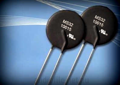
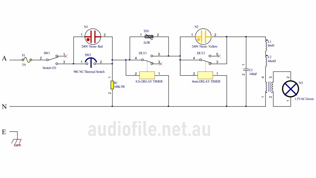
In order to mitigate against the high in-rush current, a soft-start circuit was added consisting of a small Negative Temperature Coefficient (NTC) inrush current limiter in series with the eraser mains supply connection. The NTC was in turn bypassed by a timed relay with normally-open contacts bypassing the NTC after about 500ms.
The peak inrush current is limited to about 20A with this arrangement. An NTC is not really necessary when bypassed by a relay and an ordinary power resistor would have sufficed, however, an NTC is fail-safe in the unlikely event that the bypass relay was to fail
With the reduced in-rush current it became possible to add a few extra features to the eraser:
- A timer cut-out to switch the unit off automatically if left on
- A thermal switch to operate if the coil winding gets too hot
- Indicator lights to show if the timer cut-out has operated or if the over-temperature cut-out have operated
Typical NTC inrush current limiting devices
Schematic drawing of the Degausser
Cut Outs:
Another timed relay with normally-closed contacts counts down from the time the eraser is switched on and disconnects the mains supply if the unit left on for more than 5 minutes. The timer can immediately be manually reset by switching off power and restarting. An amber neon lamp is connected across the relay contacts to indicate to the user if the time-out relay has tripped
A 90C thermal switch was placed in series with the eraser mains supply to remove the supply voltage if the coil is left running and its temperature becomes too high. This could happen if the time-out relay failed or if the operator repeatedly overrides the time-out period. The thermal mass of the coil winding is small and the coil could potentially overheat quite quickly if left on. The thermal switch was mounted on and pressed against the inside of the coil winding as well as being thermally insulated from the core to give a true measure of coil temperature. A red neon indicator lamp is wired across the thermal switch to indicate if the thermal switch has been tripped. In the tripped, open-circuit state there is no path for current to flow to allow the red neon indicator to illuminate so a 100k resistor to the mains supply return circuit was added after the thermal switch
Fault Modes:
Interestingly, while the basic Weircliffe Model 7 Magnetic Tape Bulk Eraser is of very simple design, once the fault modes are considered, the unit quickly becomes much more complex. It is often the case that a relatively simple function has many fault and/or failure modes that need to be considered and mitigated against and this is one of the hallmarks of good engineering practise. The traditional method for identifying, tracking and mitigating these issues is with a Failure Mode Effects Analysis (FMEA)
The original green, incandescent pilot lamp powered from a secondary coil winding was retained to indicate normal device operation
The current path through the final tester implementation is; power switch thermal cut-out switch, in-rush current limiting circuit, 5min delay timer, coil winding
Conclusion:
Now capable of handling 10.5″ reels of tape, the Weircliffe Model 7 Magnetic Tape Bulk Eraser now:
- Still erases tape!
- Uses a LOT less power
- Still makes lots of noise
- Weighs slightly more than a ton, around 16kg


